Eng-Tips is the largest engineering community on the Internet

Intelligent Work Forums for Engineering Professionals

Datum Reference 4

Status
Not open for further replies.

AlexFH

Mechanical
Apr 29, 2024
3
0
0
NO
Hi,

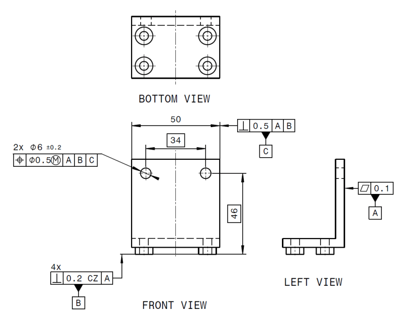
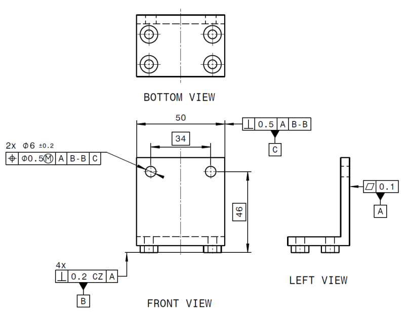
In this case, Datum B is a group of four faces. Should I use B or B-B?

I have always used B in cases where I use the CZ modifier, and in my mind B-B should not be necessary to use since the four surfaces shall be interpreted as one surface already.
But recently one of my colleague attended a GPS training course and the trainer told my colleague to use B-B. So I'm a bit confused, because I cannot find any examples of this in ISO. I have used "B-B" for e.g. hole patterns. So if anyone can point me to where I can find what I'm looking for in the standard, I would appreciate it very much.

I'm working with ISO GPS, but I assume there are some similarity between ISO and ASME in this regard.

a)
Datum_B_image_rswf9b.png


b)
Datum_B-B_image_q7crv0.png
 
Replies continue below

Recommended for you

Unfortunately, in this area (and in a quite few other areas) the two standards are not similar.

Per ISO, B-B is the correct choice. See ISO 5459:2011, if you have access to it.
 
Yes, I have access to ISO 5459, could you point me to the paragraph in the standard where I can read about this?
Could potentially end up with a pretty nasty(in my mind) tolerance box, like |A-A|B-B|C-C|, but I guess that how it should be.

Out of curiosity, how is this done different in the ASME standard?
 
I am NOT an ISO expert!!!
With my limited expertise in this area I would naswer answer your original question as follows:
You might need to use B-B if you are using CZ inside the tolerance indicator.
You don't need to use B-B (and you have to use only B) if UF (United Feature) is used outside of tolerance indicator.


The UF or "united Feature" modifier will be used when the intention is to treat the entire profile as a single feature.
I think the reason for making both CZ (uniting the tolerance zone) and UF (uniting the features) options available is that there may be a requirement to treat some or all of the profile as a datum feature. A datum marker attached to part of the profile when the CZ modifier is used, would be identifying that single individual feature as a datum feature. A datum marker attached to part of the profile when the UF modifier is used, would be identifying the entire profile as a datum feature.


Feel free to shoot down my above statements. I am willing to learn more and the best way to do that (learn) is to make mistakes :)

 
When UF is used instead of CZ, then yes, B-B reference will not be needed, i.e., single B will suffice.

And while using UF makes sense on the original drawing, it should not be used for datum pattern of holes, unless the holes are nominally coaxial and are of the same size.

I am quoting para. 3.9 in ISO 1101:2017 below to support the last statement:
"Note 2 to entry: The definition of a united feature is intentionally very broad to avoid excluding any useful applications. However, it is not intended that a united feature can be used to define something that is by nature several separate features. For example, building a united feature from two parallel, non-coaxial cylindrical
features, or two parallel, non-coaxial rectangular tubes (each built from two perpendicular pairs of parallel planes) is not an intended use."
 
I'm not familiar with the ISO standard but does it have the same principle of datum hierarchy as the ASME standard?

Primary - 3 points of contact
Secondary - 2 points of contact
Tertiary - 1 point of contact
 
I have not used ISO.
I have also never seen B-B used. That's confusing to me.
Datum B is attached to the perp symbol, and reference all 4 surfaces.
So, |A|B|C| should be sufficient.

Chris, CSWP
SolidWorks
ctophers home
 
If they wanted to be more explicit it should have as many references as there are features. Example B-B-B-B.

Or a count, B-120, potentially in case the tips of a heat sink pins are the reference.
 
3DDave said:
If they wanted to be more explicit it should have as many references as there are features. Example B-B-B-B.

I think you still have to use nx (number of times the feature is counted in the pattern), but B-B is just to jump in front of the end user's eyes that the intent is to use the pattern. I guess B-B is that all it does. No info how many features, etc.
Then after that information about using the pattern is communicated, you have to understand how many features are used in that pattern (by reading the nx multiplier)

 
It's redundant. It might as well be really redundant. Maybe they are holding that back to bake into the next version for another round of expensive standards publications.
 
Thank you all for in-depth and helpful answers. It seems that UF is what I have been looking for and have been using CZ when I really should have been using UF. I will look more in to this.

I came across another use of UF that confuses me a bit.

As stated in para. 3.9 in ISO 1101:2017 Note 2:
"However, it is not intended that a united feature can be used to define something that is by nature several separate features."

Then I see in para. 9.1.2 That UF is used with the "all over" symbol that unites multiple features. Isn't this contrary to the statement in 3.9?

From ISO 1101:
ISO_1101-2017_pkt._9.1.2_Fig_55_fmpz8j.png
 
AlexFH said:
....Then I see in para. 9.1.2 That UF is used with the "all over" symbol that unites multiple features. Isn't this contrary to the statement in 3.9?...


Per UF definition: compound integral feature which may or may not be continuous, considered as a single feature.

I would argue that the figure 55 is a single feature and since "all over"--double circles-- (not "all around") symbol is used that makes the entire part a "single feature" so UF would be the appropriate symbol to be used.
And of course, it is correct, because the standard says so :)

 
If CT (Common Tolerance) in the last image posted, was changed to UF (United Feature) why would it be wrong and how would it be different from CT?
 
Burunduk said:
If CT (Common Tolerance) in the last image posted, was changed to UF (United Feature) why would it be wrong and how would it be different from CT?

Where did we say it is wrong?
Is your question for academic purpose, right? Just to be creative and understand the comparison between those two ISO GPS modifiers?


I wasn't suggesting someone said it's wrong; it's just that my impression is that in ISO GPS, they never define two different symbols for the same thing. They have a bunch of symbols, but each one has something unique about it, even if it's just some fine details. Yep, my question is more on the academic side.
 
Burunduk said:
I wasn't suggesting someone said it's wrong; it's just that my impression is that in ISO GPS, they never define two different symbols for the same thing. They have a bunch of symbols, but each one has something unique about it, even if it's just some fine details. Yep, my question is more on the academic side.

Ok. Understood.
Then I would say that the INTENT of UF was not to be applied for those "regular" features of size. That is reserved for CT which is called common toleranced feature of size.
I guess you can use UF to be creative...but again that is my opinion.
(since you already have CT, I might not see why would you want to use UF, but anyway)
 
Ok, thank you,
But then, why did they use UF and not the "common toleranced feature of size" modifier, CT, on this one?

Screenshot_20240515_202227_Drive_cd7hts.jpg


The example is from ISO 1101:2017. Looks like an end view of a simple spline shaft, it should be considered a feature of size.
 
Status
Not open for further replies.
Back
Top