Continue to Site

Eng-Tips is the largest engineering community on the Internet

Intelligent Work Forums for Engineering Professionals

  • Congratulations The Obturator on being selected by the Eng-Tips community for having the most helpful posts in the forums last week. Way to Go!

Datum selection and dimensioning - quadruple saddle clamp 2

Status
Not open for further replies.

itar

Aerospace
Jun 11, 2024
4
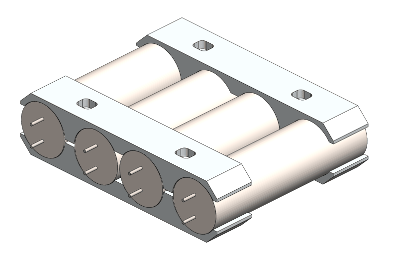
I have a part that could be described as a "quadruple saddle clamp". Four of these parts will be used to clamp four cylindrical battery cells together (each cell looks like radial electrolytic capacitor, but 18650 sized).
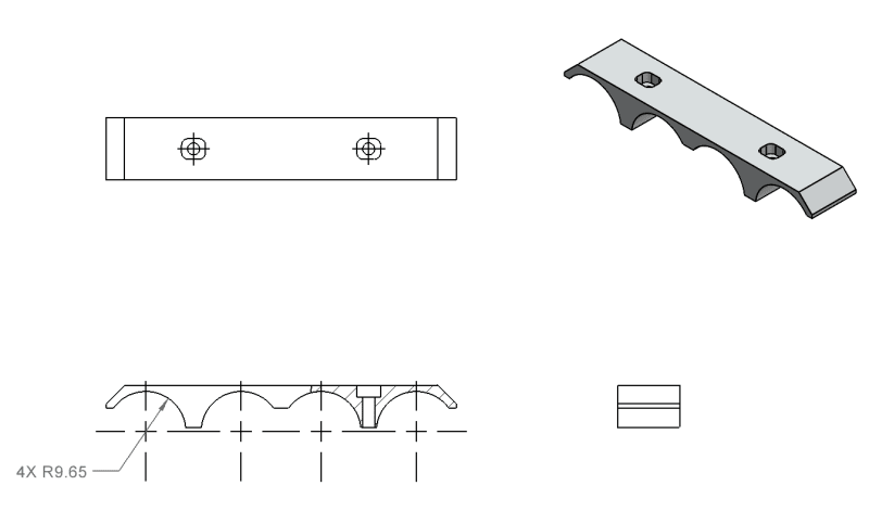
clamp_o8lp98.png

simplified_assembly_scudlu.png


I'm mainly concerned with controlling the positions of the cells relative to each other and making sure they are parallel, so that the leads can be inserted into a mating PCB without excessive stress. Perpendicularity between the cells and the end of the clamp is secondary, and the rest of the profile that is not in contact with the cells does not need to be tightly controlled.

Can anyone recommend an appropriate set of datums for this? I don't use GD&T often, so I'm a bit out of my depth here.
 
Replies continue below

Recommended for you

This part is symmetrical in two directions. So, it is better to design it with these "symmetry" intents.

I would use datum features below for datum A, B, and C:

Datum feature for datum A: Top surface;

Datum feature for datum B: Center plane (or derived medium plane) of the width;

Datum feature for datum C: Center plane of the length.

Best regards,

Alex
 
The centerplane of B (or C, for that matter) is not a functional datum feature. The as-produced variation in hole location will not be symmetrical, it will be to one side or the other of that theoretical plane and, since there isn't an indication to the installer which way that variation is, the part can still go in the wrong way round.

If there was an orientation mark or feature to identify one face to be used as a datum feature, then the part width tolerance could be very large.

If the centerplane is used the part width tolerance needs to be small if the clearances with mating parts is small, otherwise for wide parts, which will be nominally centered on the screws/fasteners, the excess width will have that face farther out than for narrow parts, reducing that small clearance.
 
As I said, the symmetry is a design intent. So, OP needs to design it for assembly (DFA).

Unless this is a prototype, this part will be casted, or forged and machined if necessary.

Best regards,

Alex
 
3D,

"The person who may need to know is the installer." - You didn't mention it until I pointed out the problem.

Also,
"Burunduk, do you see in the application proposed a problem for the installation if a non-contacting surface is oriented one way or the other?" - This indicates you didn't think there was a difference whether one side is used for datum reference or the other. Again, not until I pointed out the problem.

Functionally, the risk is not equal from both sides. That said, I agree with Jassco. The symmetric geometry may imply a design intent. There are advantages to designing it for assembly either way, but it comes with the cost of tighter size tolerance on the datum feature width. That tighter tolerance and the location tolerance for the mounting holes should take into consideration the clearance needed on the critical side.
 
Hi, Burunduk:

Well, OP does not need tighter tolerances for over-all sizes. He or she just needs a tighter tolerance for those 4 profiles of surface as a pattern. The whole pattern can shift by whatever amount that he or she can live with.

Best regards,

Alex
 
Jassco,

You seemed to suggest using the part width as a datum reference at RMB.
Widths as datum features RMB need to be somewhat accurate to be stable and reliable.

Actually we don't have enough information about the application to suggest an optimal datum scheme. But if the width is insiginificant it shouldn't be used as a datum feature at all. I did get the impression that the front side ends up at a small clearance from another component. Then if the front and back sides are interchangeable because of the symmetry the size between them better be accurate.
 
""Burunduk, do you see in the application proposed a problem for the installation "

is my way of saying `"Here, horse, this is water. Can you drink it?"

You can lead a horse to water but can't make them drink.

The OP defined the intent. Wrote it right out. This will be your third time to coat-tail ride after I tell you exactly what to look for. See if you can spot the intent.
 
3D,

When you didn't make any conclusions from Op's "Perpendicularity between the cells and the end of the clamp is secondary" is where you missed the issue with the side face. You assumed anyway that since it's not in contact with another part, it doesn't matter which side is used as a reference. This is what your question indicated. Then, after I pointed out the significance, you introduced the nonsense that only the installer should care, but everyone else doesn't have to.
 
In fact I did not. My initial suggestion was that the surfaces not in contact use those in contact as datum feature references.

Haven't found the clearly stated intent and just back to sniping again?
 
"Initial suggestion"?

"However, I would not make that face the primary datum feature. It is small and, when used as the lower clamp part, doesn't contact the mounting surface. The large flat surface should be the primary datum feature as it does make contact with and is responsible for orienting the part against the mating surface where it is assembled" -Came only after I started to point out the problems and you jumped on the bandwagon. Before that you were busy beating around the bush.

Funny that you say I'm the one missing the stated intent after you didn't see the problem until I put it right under your nose.

 
3D,
The OP didn't mention any interface of the clamps to anything else other than the battery cells. The only hints about installation are the pair of holes + rectangular slots and the mention that perpendicularity between the arcs receiving the cells and the end face is important, as also reflected by the datum choice in his drawing. Clearly the significant orientation is relative to the side facing the PCB. Even if that face doesn't contact anything, the clearance may not be huge, otherwise, the requirement would not be mentioned.

This is why I brought up the issue of differentiation between the two sides if one of them is used as a datum feature as in the Op's drawing. You overlooked it until I mentioned it, even though you were commenting here first, and considering you claim to be a "D&T consultant", that's unfortunate.
 
"Perpendicularity between the cells and the end of the clamp is secondary, and the rest of the profile that is not in contact with the cells does not need to be tightly controlled."

"I also want to avoid any ambiguity, since the part is symmetric."

Those are the requirements. A symmetry requirement is not implied. Avoidance of ambiguity is required.

That I do not spoon feed you doesn't mean I overlooked it.
 
"I also want to avoid any ambiguity, since the part is symmetric."

But after that, you didn't address the symmetry-related ambiguity in that drawing. I was the one who pointed out the problem when I joined the discussion. You responded to the drawing before that and didn't help the OP solve it because you overlooked it. That's not good for someone who identifies as a "D&T consultant." If you didn't overlook it but still chose not to mention it, that's even worse.
 
itar,

The reason this is not a commonly available clamp system is that it is nearly impossible to provide uniform clamping on all four cells at the same time unless the clamp is very conformable. The cells are stiff, the thin layer of tape is stiff, and the bracket is stiff; none of it is conformable.

What will likely happen is the assembler could spend a long time chasing the one cell or two cells that are loose.

This works fine for just two cells - that's a teeter-totter arrangement which has a great deal of adaptability.

Take the case when the outer two slots are exactly the right depth and curvature but are a little too far apart. This will cause the cells to be clamped farther apart than if those outer cells were the perfect distance from each other, which means the middle cells won't be clamped with the same force.

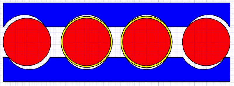
quad_trwixp.png


The tape comes only in a minimum thickness, so adding tape to the middle cells to make up for the gap may exceed the size of the gap and now the outer cells aren't captured.

Now imagine that the two on the ends are offset, but one of the middle ones is only slightly off set. Add tape to that and it can be too much and now the end cell next to it is loose. Add tape to that one and now that middle one is loose.

Even if the tape is exactly right, per the above image, the majority of the clamping force is taken by the two outer cells while the inner cells have the bracket potentially digging into the tape and causing it to slide out of the way. Maybe tight today, loose tomorrow.

Unlike a teeter totter, where the forces on the ends are exactly (or nearly so) balanced on the fulcrum between them, the amount of force on the cells will depend on how much the clamp bends and exactly where the bending takes place.

The direction to go from here is a discussion with the FEA people to do a non-linear contact analysis to apply the same force to each of the cells with different amounts and direction of variations and amounts of filler tape.
 
Status
Not open for further replies.

Part and Inventory Search

Sponsor