Continue to Site

Eng-Tips is the largest engineering community on the Internet

Intelligent Work Forums for Engineering Professionals

  • Congratulations KootK on being selected by the Eng-Tips community for having the most helpful posts in the forums last week. Way to Go!

DC 250KW motor Field overheating urgent! 6

Status
Not open for further replies.

Sumair786

Electrical
Jul 24, 2022
21
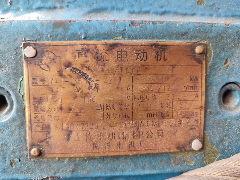
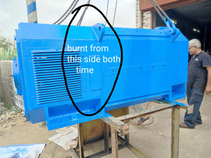
Hi, i need help i rewind motor field winding but the issue is all 4 fields burnt after some time but only half side of the field the other half of the field was as good as new recheck connection all are correct field voltage as per nape plate is 180 volts with 23.5 amp when the motor runs on DC drive field voltage keep increasing minutes after minutes but Ampere remains same. Drive is working fine i have checked it,
thanks
 
Replies continue below

Recommended for you

If the drive has field current regulator, the field voltage will increase as the temperature (and resistance) of the winding increases.
Only half the field is burnt – the inner windings? May be due to too thin wire being used.
Some field windings are wound with larger wire dimensions in the inner windings as they have less cooling. This makes rewinding difficult without the motor winding data. Nameplate data 180v 23.5A is when winding is warm,
 
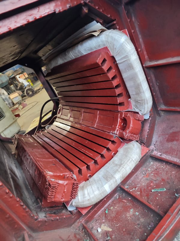
Screenshot_2022-07-25-03-17-48-400_com.miui.gallery_qkyp0e.jpg
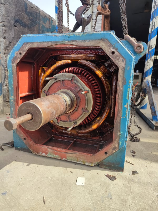
Screenshot_2022-07-25-03-18-05-010_com.miui.videoplayer_iwijwe.jpg
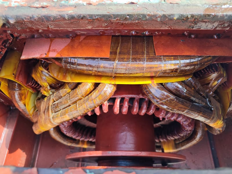
[img
 
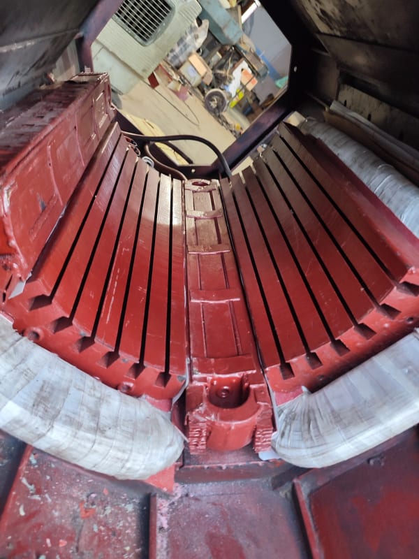
Never seen the winding+core assembly being removed like that. If you did the same after rewinding, the winding was already damaged by the time it went into the stator frame.

Muthu
 
Agree with Edison, it's a novel and mostly destructive way to remove the field windings.

It's understandable however because of the sequence in which the coils must be assembled
during the rewinding process.

Initial guess to the original problem: Obstructed or lack of cooling air flow.

It looks like one of the bearings in the device may be a 7220, but have to admit
the name plate is most difficult to interpret.

John
 
Often all the poles are pulled out so that the access and rewinding of the main poles goes faster.
Problem is how to return the sheets under the poles, which can affect the geometry and behavior of the DC motor under load .
You should always rewind all the windings of the main poles, bearing in mind that they all suffer heating, and if you don't do a Baker test, you can't be sure that the other windings don't have a problem.
It looks like there is definitely a cooling problem and increasing the amount of air will solve the problem.
 
Sumair An overheating issue on one side of the field pole assembly means one of three things.
1) Winding fault on that portion of the field winding (likely turn-to-turn fault, although could be turn-to-ground). Local area around the fault will get extremely hot, but the coil (as a whole) will not.
2) Poor heat conduction and/or convection on the "hot" side. Most likely culprit is having the pole too close to the adjacent one so either the pressure drop through the gap is too large, or the coils of adjacent poles (in this case, main pole and interpole) are touching. Alternative culprit is having a blockage at (or near) the end where cooling air should be entering the space between windings. This second "blockage: could be a misplaced baffle.
3) The main field winding is in direct contact with the interpole winding (see #2 above). The heat is not coming from the main coil, but rather from the interpole coil which carries a LOT more current (and can exhibit a subsequently higher surface temperature).

As BVSM22 noted, a field supply which is CURRENT REGULATED will hold a current setpoint and allow the applied voltage to vary. As the coil(s) heat up, the resistance increases - which in turn requires more voltage to push the same current through the circuit.

Last thing - it looks like the sling is looped through the end of a winding (either interpole or poleface). In either case, this is a pretty sure bet there will be some sort of damage to one or more windings in the machine - these are not meant to be "lifting points".

Converting energy to motion for more than half a century
 
Does the motor have a high speed blower? And was it running? I presume the louvres are the hot air outlets. Is the outlet air forceful? Did you fix winding RTD's for the shunt and interpole windings during rewinding to monitor temperatures?

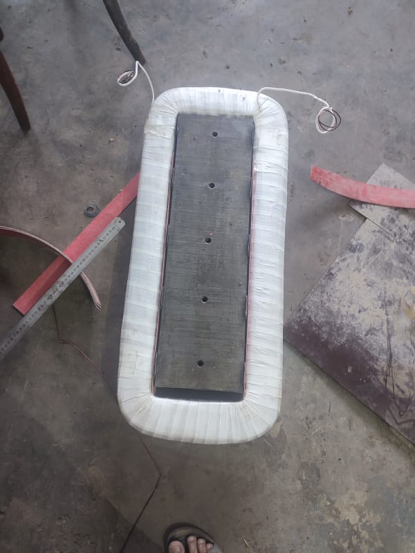
At 23.5 Amps, I would expect custom designed rectangular conductors. If you replaced it with standard round wire, you lost a lot of copper area.

Shunt field winding is like a room heater (in your case, a 4 KW heater) and hence needs a constant cooling even when the motor is running on no load.

And no, you cannot use your weak copper winding for lifting the poles out or putting the poles back in.

Muthu
 
Only interpol windings are original shunt and field winding are rewound,
it was in round wire originally SWG 14
Used same 99.99% copper
All the spacer below Field winding cores are intact.
Yes amperage remain same but voltage keep increasing and field temperature touching 100°C at 280Volts 23.5amp in just half an hour while on load, but checked off load it remains same but shunt, armature and even commutator temperature is around 60°C
Thanks for you valuable time
 
Sumair Please check your circuit connection to THE ORIGINAL DESIGN. My guess is that you now have the coils connected in series (1-2-3-4), instead of two parallel paths (1-3, 2-4). The series connection would give you the correct current as that is what you're regulating on, but would require roughly twice the voltage of the "original design" connection.

And I hate to say it, but errors in stamping data on the nameplate have occurred over the years.

Looking at your last set of images - I would say the field coil is built out too far from the main pole steel and there is correspondingly no room for airflow between main coil and interpole. For reference - it is fairly normal for the the larger OEMs to build their coils such that outside edge of the winding runs outward along the same radial line as the edge of the pole shoe (i.e., the coil does not overhang the pole shoe AT ALL).

Converting energy to motion for more than half a century
 
Also, please check that motor no load speed, at armature voltage/field current = 440v/23.5a corresponds to not less than the nameplate's 1200rpm
 
280 V, 23.5 A or 180 V, 23.5 A, which is it?

How many 14 swg? What was the shunt field connection, series or parallel?

What was the no-load speed after rewind at 23.5 A?

Photos of the failed half coils?

So many questions.


Muthu
 
Field connections are 2 parallel
Voltage is 180 and motor starts at 175 volts but by the time goes it increases and after half an hour it reaches 280 volts 23.5 amps
SWG 14 single wire parallel connection
Will answer all the questions you guys have i just need to solve this problem ASAP thanks
 
Coils weights are same as original so there won't be a guage or turns difference
 
At 180 V, what was the field current and speed?

At 280 V, 23.5 A, what was the speed?

14 swg in 2 parallel is ok provided the polarity of shunt field was maintained. Post a sketch of how you connected the shunt field coils.

Muthu
 
Speed remain same from 180 to 280 volts 500RPM
In the nameplate its written
440 Armature volts
600 Armature amps
180 Field volts
23.5 Amp
But RPM is 500/1200
We are running it on maximum 500RPM on load is there any problem with this?
Posting winding connections in a while
 
Status
Not open for further replies.

Part and Inventory Search

Sponsor