Continue to Site

Eng-Tips is the largest engineering community on the Internet

Intelligent Work Forums for Engineering Professionals

  • Congratulations KootK on being selected by the Eng-Tips community for having the most helpful posts in the forums last week. Way to Go!

DC model motor and viscous damping: behavior inconsistent?

Status
Not open for further replies.

jblc

Mechanical
Apr 2, 2009
24
I'm unclear on why a motor model's step response isn't what i'd expect, when a damping coefficient (b) is varied.
With equivalent closed loop gains, I'd expect a shorter risetime for a motor with less damping...but instead, it looks like closed-loop step responses are identical to that of a higher damped system.

Say there's a DC motor with a Current I input, Angular Velocity θ_dot output. Optional Example: the "Load" block in [link mathworks.com/help/control/examples/dc-motor-control.html]Link[/url] (Ignore the Armature block).

Then θ_dot /I = K[sub]t[/sub] / (Js + b).
b is the damping coefficient, J the moment of inertia. Higher b means more damping, lower means less damping.

Prelim Question) In terms of step responses given a pole placement, write K[sub]t[/sub] / (Js + b) in time-constant form K / (Ts+1) :
(K[sub]t[/sub]/b) / [ (J/b)s + 1) ] --> T = J/b. Since T = 1/(-Pole), if T gets smaller as b grows larger, the Pole gets larger...so faster response?
Which doesn't make sense. Larger b should lead to a pole closer to the origin (since larger damping == slower response). Why is this not consistent?

1) Now, regarding the identical closed-loop responses. Say b = 1e-5, K[sub]t[/sub] = 10, J = 1. Transfer Function TF =
10
---------
s + 1e-5

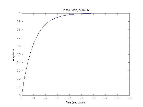
Open-loop and closed-loop step responses, with a simple closed-loop feedback gain of 1:
(See Matlab code at end of post if desired)
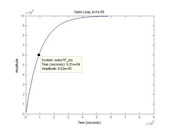
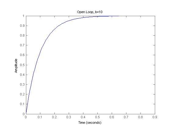
motor_normal_b_OL_eeao5l.jpg

motor_normal_b_CL_lhvgpf.jpg


2) Say b decreases by a factor two (less damping) with b = 1/2 e-5. Transfer Function TF =

10
---------
s + 0.5e-5

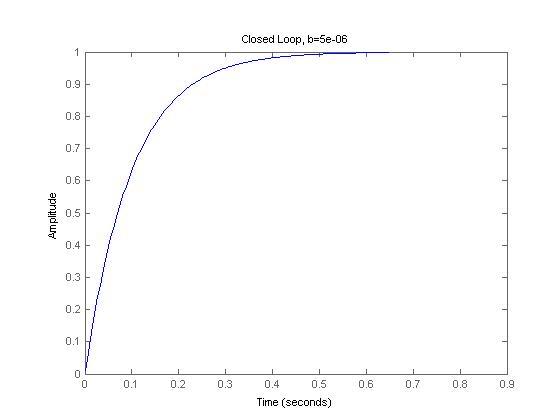
Open-loop and closed-loop step responses:
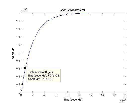
motor_half_b_OL_avorjl.jpg

motor_half_b_CL_q06dfm.jpg


3) As expected, for open loop responses, the time to reach the same amplitudes (eg ~6e6) is indeed shorter for the lower damping case.
But the closed loop responses are identical.
Why isn't the risetime to 1 faster with lower b?


Code, just in case:
b = 1e-5; %or 0.5e-5
J = 1;
Kt = 10;

s = tf('s');
TF = Kt / (J*s + b);
step(TF);
title(['Open Loop, b=' num2str(b)]);
K = 1;
TF_FB = feedback(TF*K, 1);
figure;
step(TF_FB);
title(['Closed Loop, b=' num2str(b)]);
 
Replies continue below

Recommended for you

Prelim question) The damping coefficient increasing does make the system respond faster during the open-loop transient, but reduces the gain (TF numerator) of the system so that it will spin slower by a factor of b for a given current. Look at the original differential equation Jdω/dt+ bω = K[sub]t[/sub]I - damping produces torque opposing angular velocity, not angular acceleration (which is opposed by J, the moment of inertia). Compare your final open-loop plots - the second one with 1/2 the damping coefficient has twice the dc gain, but takes twice as long to reach steady state. Alternatively, you could think of it this way: if there is 1/2 the damping coefficient, it will require 1/2 the current to achieve the same steady-state angular velocity but it will take twice as long to reach steady state. One last argument here: if you multiply both sides of the original differential equation producing the TF by angular velocity, you have P[sub]load[/sub]+P[sub]loss due to damping[/sub]=P[sub]in[/sub]. Therefore, an increase in damping coefficient also reduces the efficiency of the system due to the loss term increasing. Maybe that's why you're thinking the response should be slower, but it isn't, for the reason described above. (I'm not really sure I've made a clear and convincing argument with this paragraph.)

3) One of the effects of negative feedback is that it reduces the sensitivity of the closed-loop transfer function to system parameter variation. You've just seen that effect using your closed loop simulations by realizing the outputs are essentially the same even with a factor of 2 difference in your damping coefficient. The closed-loop TF is given by KK[sub]t[/sub]/[Js + (b+KK[sub]t[/sub])]. The product of proportional controller gain K and motor gain K[sub]t[/sub] is high by comparison with b (10 vs 1e-5 or 0.5e-5) and dominates their sum in the denominator - meaning the closed-loop pole locations for both values of b are basically the same, and the DC gain is KK[sub]t[/sub]/[(b+KK[sub]t[/sub])], essentially 1. Hence, you get (approximately) the same step response. If the product of KK[sub]t[/sub] was closer to the value of b, changes in b would have more of an effect on the closed-loop response speed and steady-state gain.

xnuke
"Live and act within the limit of your knowledge and keep expanding it to the limit of your life." Ayn Rand, Atlas Shrugged.
Please see FAQ731-376 for tips on how to make the best use of Eng-Tips.
 
Thanks for the great reply, which is starting to clarify things!

Regarding 3), say I change b by a factor 10 to make its impact visible on feedback.
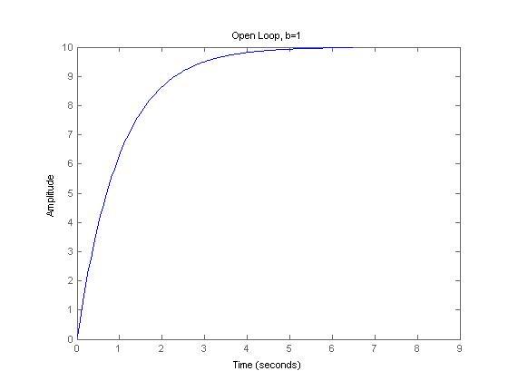
b=1 now, so Transfer Function TF = 10 / (s + 1)

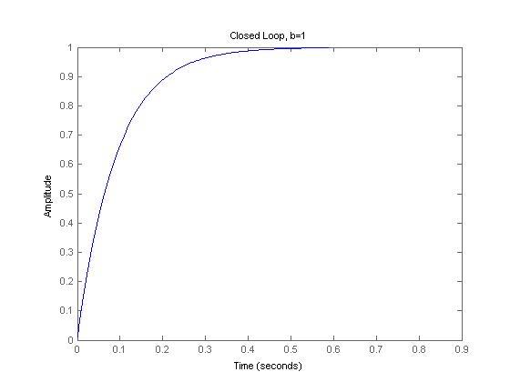
Here are the open- and closed-loop step responses, with a simple closed-loop feedback gain of 1. For closed-loop, the step input is scaled by the inverse CL-TF@s=0: ( 1/[Kt / (b+Kt)] ), to give the same final target value of 1 for both the b=1 and b=10 case for easier comparison. (See Matlab code at end of post)

motor_OL_b_1_jwxlgj.jpg

motor_CL_b_1_ratret.jpg


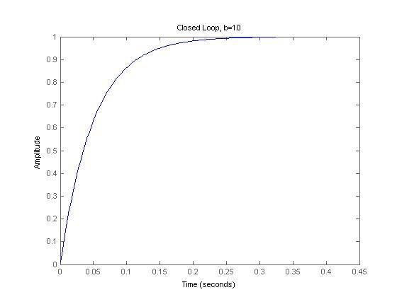
b = 10, so Transfer Function TF = 10 / (s + 10)
motor_OL_b_10_drud89.jpg

motor_CL_b_10_gztael.jpg


Unexpectedly, after scaling the step input so that both reach 1, the closed-loop risetime is longer for the lower damping case. Why is the risetime faster with higher b?

If there is no input step scaling -- that is, just keep StepAmplitude=1 -- then the closed-loop ristime of the b=1 case is indeed faster than the b=10 case, but the outputs would settle at different values: 0.91 for b=1, 0.5 for b=10. If steady-state tracking to a specific output value (eg =1) is needed, then the input scaling seems to be required, but that also causes the behavior to be opposite what's expected, as above...
I see that the SS outputs are 0.91 and 0.5 because the Closed-Loop TFs are 10/s+11 which is 0.91 when s=0 (steady-state), and 10/s+20, which is 0.5 when s=0 (steady-state), but it's not clear how to compare results, then, without input scaling...which seems to flip the behavior

b = 1; %or 10
J = 1;
Kt = 10;

s = tf('s');
TF = Kt / (J*s + b);
step(TF);
title(['Open Loop, b=' num2str(b)]);
K = 1;
TF_FB = feedback(TF*K, 1);
figure;
stepOpt = stepDataOptions('StepAmplitude', 1 / (Kt / (b+Kt)) );
step(TF_FB, stepOpt)
%above 2 lines could also be unscaled: step(TF_FB);
title(['Closed Loop, b=' num2str(b)]);
Code, just in case:
 
Here's a simpler follow-up question instead, related to the poles of a transfer function:
Between
1/(s+2) --> (1/2) / [(1/2)s + 1]
and
1/(s+4) --> (1/4) / [(1/4)s + 1],

the 2nd function has the faster pole, since T = 1/-p. Here p is the pole, and T the time constant. For the 2nd function, T = 1/4, so a = -4.
So the pole of -4 is faster than the pole of -2, so the 2nd TF has a faster response.

So far this makes sense.
BUT, with a higher viscous damping term b in the motor equation K[sub]t[/sub] / (Js + b), as b grows larger, the equation above shows a faster pole than that of a smaller b.

That is counter-intuitive, I'd expect a faster pole as b grows smaller (less friction, so faster response), instead of a faster pole as b grows larger.
At the extreme, infinite damping means no motor movement, so why does that give an infinitely fast pole? 1/(s+inf) -> (1/inf) / ((1/inf)s + 1) --> p = -inf
Likewise, zero damping seems like it should give faster response than infinite damping.

Why is this opposite of the expected outcome?
 
I think xnuke already said this, but let me try to rephrase it.

What may be confusing is that what you are calling 'faster response', is not necessarily rotational speed. If you give your infinite damping system a step input it has fast response because it's already at it's steady state speed! If you have a system with low damping, and all other parameters identical, it will take a long time to reach it's steady state speed because the speed will be much greater.
 
Thank you for the response, that clarifies that question! (Together with xnuke's reply).
 
Status
Not open for further replies.

Part and Inventory Search

Sponsor