Continue to Site

Eng-Tips is the largest engineering community on the Internet

Intelligent Work Forums for Engineering Professionals

  • Congratulations IDS on being selected by the Eng-Tips community for having the most helpful posts in the forums last week. Way to Go!

Deck joists attached to floor joists

buleeek2

Structural
Jan 9, 2025
3
Hello everyone,

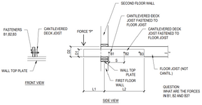
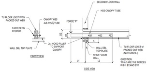
Every once in a while I need to design a deck with joists fastened to the side of floor framing. See attached. I am wondering what your approach would be to come up with shear forces in bolts B1, B2, and B3.
See attached and thank you for your input.
 

Attachments

  • FORCES IN BOLTSr.pdf
    33.6 KB · Views: 7
Replies continue below

Recommended for you

I would assume all the uplift is being resisted by bolt B3. I would design B3 to resist the force: P x L1 / L2. The other bolts, B1 and B2, would just be there to provide lateral stability for the deck joist. This approach should be conservative.

In reality, I'm not sure how the loads would be distributed to the bolts. I can speculate that perhaps most of the load would want to go to bolt B1 initially since it would technically be the stiffest load path. Since the lever load to B1 would be very high, I imagine the wood grains would crush at the bolt and the resulting deformation would allow most of the load to be redistributed to bolt B2. Then the same would occur at B2 and most of the load would end up at B3. The end result is maybe a linear distribution with B3 taking 2/3 of the uplift, B2 taking 1/3, and B1 taking close to zero. Again, just speculation.
 
Isn’t this just a continuous beam? Any number of indeterminate analysis methods will solve for the reactions. Model it once as if the bolts provide rigid support and then again idealizing the bolts as spring supports, to account for wood crushing and/or bolt plasticity. The reality is somewhere between the two, depending on how stiff you model the springs.

You can manually check for which of the dowel limit states from the NDS controls (ZI, ZII, etc.). Select a spring stiffness based on which failure mode happens first (i.e., wood crushing, etc.).
 
Also, don't use bolts if you can avoid it. Use a cluster of smaller diameter screws at the back end (where Bolt 3 is), and then a staggered pattern down the length. Wood responds better to lots of small fasteners than to a few big ones, where crushing comes into play a lot faster. There are limits, of course, and too many will just tear the wood to pieces, but putting 6 or so 1/4" self drilling structural screws in lieu of a single 3/4" bolt will have much better performance.
 
I would assume all the uplift is being resisted by bolt B3. I would design B3 to resist the force: P x L1 / L2. The other bolts, B1 and B2, would just be there to provide lateral stability for the deck joist. This approach should be conservative.

In reality, I'm not sure how the loads would be distributed to the bolts. I can speculate that perhaps most of the load would want to go to bolt B1 initially since it would technically be the stiffest load path. Since the lever load to B1 would be very high, I imagine the wood grains would crush at the bolt and the resulting deformation would allow most of the load to be redistributed to bolt B2. Then the same would occur at B2 and most of the load would end up at B3. The end result is maybe a linear distribution with B3 taking 2/3 of the uplift, B2 taking 1/3, and B1 taking close to zero. Again, just speculation.
Wood crushing and yielding to get the load where you want it sounds like something I would want to avoid.

Why not just put a couple fasteners right over the double top plate and then fasteners at the end (B3) ?
 
Wood crushing and yielding to get the load where you want it sounds like something I would want to avoid.
I think that's making it seem more dramatic than what might actually occur. With that said, I would likely do something more along the lines of what pham suggests with many smaller diameter fasteners (nails or screws) assuming that can work with the loads. Maybe just 16D nails or wood screws staggered at 6" o.c. In this case I would have a group of fasteners around the location of bolt B3 which can take the load there.
Why not just put a couple fasteners right over the double top plate and then fasteners at the end (B3) ?
I would do that and have fasteners between. I'd be a little concerned with buckling if there was nothing from B1 to B3.
 

Part and Inventory Search

Sponsor