Eng-Tips is the largest engineering community on the Internet

Intelligent Work Forums for Engineering Professionals

Declaring steel knee brace to take only 20 kips axial load as bolt capacity inadequate 11

Status
Not open for further replies.

NewbieInSE

Structural
Dec 19, 2019
234
0
0
BD
Dear Engineers,

I have attached a figure herewith which will be beneficial in understanding my query.

Member_to_carry_a_certain_amount_of_load_only_py1fvk.png


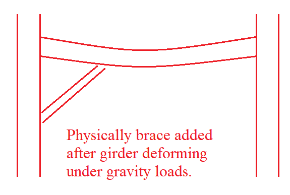
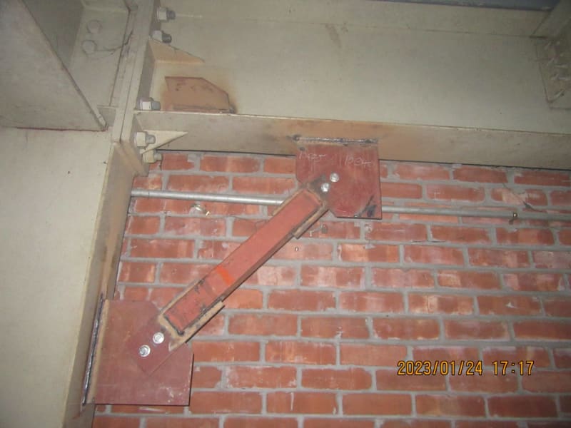
As you can see, the steel building is three-storied, and some knee braces were added previously to avoid retrofitting of some main steel beams (girders). The purpose was to reduce the length of the member and produce less loads in the girder, which was achieved well.

However, the knee braces' connections are not capable to resist the loads transferred to them in ETABS.
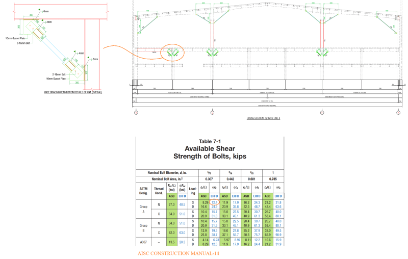
Two bolts can carry about 24.8 kips of shear load.

Whereas in FEM (ETABS) we get a force of about 45 kips due to gravity load combos. Also in some gravity+lateral load combos, the applied load exceeds the capacity of the connection.

Is there any method by which we can declare that these knee braces are provided just to carry say 20 kips forces and the latter forces are not intended for it, equilibrium will be established for the whole structure considering this trade-off (knee braces taking only 20 kips).

Is this justifiable??

This is an existing building, we don't want to apply weld and ignore those bolts to carry the applied loads, because it will be massive work and the factory is in operation.

Thanks....
 
Replies continue below

Recommended for you

You could reduce the stiffness of the member in ETABS so it attracts less load, and see what effect that has on the rest of the structure.

But then you need to get comfortable with whether it REALLY attracts less load.

DaveAtkins
 
But then you need to get comfortable with whether it REALLY attracts less load.

Also need to be comfortable with the failure mode (bolt shear is a brittle failure, while some others are not), the circumstances of that failure (does it only happen under seismic loading?), and how the rest of the structure responds if it does fail (does it flex out of shape or collapse?)

Rod Smith, P.E., The artist formerly known as HotRod10
 
BrdigeSmith said:
circumstances of that failure (does it only happen under seismic loading?), and how the rest of the structure responds if it does fail (does it flex out of shape or collapse?)
No, not only seismic loading. For example 1.2DL+1.6LL, and some seismic combos also are responsible.
The failure mechanism? The girder below which the knee is may yield.
 
No other tough failure things. The structure is pretty stable against all loads but has some local member failing (exceeding fy) issues.
 
In short, no, you cannot. As Dave and Rod mentioned, there are things that can be done for extenuating circumstances, but these are fairly advanced and you have to carefully consider the expected performance of the structure and the expected behavior before, during, and after failure. They are not typically used for normal load cases/combinations, but rather for extreme events. Given your title, they aren't the sort of thing you should be doing/deciding. That should be for your boss.

If you need to make the call, you need to redesign the connection to take the expected load.

There isn't a crane running on that girder, is there? If so, remove that detail and increase the girder size right away. That used to be a common detail for crane rail girders, until a lot of them started failing.
 
This is a good question.

What you're describing sounds a lot like Plastic Design by the Statical Method. For example, in a continuous beam, you would say the moment is Mp in this or that location, and go from there. This is only allowed for compact sections because a noncompact or slender section wouldn't hold Mn as the hinge rotates during redistribution. With bolts, there's no great yield plateau, so don't do as you proposed.

Then I realized that such methods are used all the time in connection design -- with bolts. See the discussion in the AISC Design Guide 29 Section 1.2 on the Lower Bound Theorem of Limit Analysis. You basically declare what load goes where. If statics is satisfied and Ru<=phiRn for everything, then the design is OK. A lot of those limit states are ductile, but bolt shear is usually in the mix. Thus, I'm not sure why this philosophy can be used for connections, but not for your case. Maybe there's an obvious reason and someone can enlighten me.

Still, something seems wrong about it, and I wouldn't do it. I'd be looking at changing the bolts to A490-X or field welding to achieve the 45 kips.
 
PhamEng said:
If you need to make the call, you need to redesign the connection to take the expected load.
Hmmm well, this is already in place. SO it is not possible to redesign, at best we can weld around the plate to achieve the desired connection strength. About crane passing, No, it is a production floor, 84 psf LL.

271828 said:
I'd be looking at changing the bolts to A490-X or field welding to achieve the 45 kips.
Hmmmm. could be possible to replace by doing some field works.

How about this as follows,

Brace_added_after_beam_deformation_kwl5rh.png


Since the brace had been added after the girder deflection, cann't we ignore the gravity load from calculatoin and design for the factored lateral load part??
 
I think you can make that case for dead loads but not for live loads.

I expect that was how the originally retrofit design was carried out - and I think it is generally appropriate.
 
The load in those types of kneebraces is often due to gravity load compression. If the braces were installed after some of the gravity loads were applied, then by all means exclude those loads from the brace compression calculation.

Another thing which contributes to the brace load is the stiffness of the brace on the opposing side of the column. Removing (or excluding) the opposite-side braces may reduce the brace load since the force is not "balanced" through the column by the opposing brace. This will increase the column flexure and reduce the overall frame stiffness, so you will need to look out for that.

I don't think we really understand how these systems act. Wood barns have been built for 200 years with these kneebrace systems for lateral stability.

I don't have any proof, but my general feeling is that these systems are somewhat self-limiting. If the braces are overloaded in compression, the bolts plow in their connection plate holes a little and the beam sees a little more of the gravity load flexure. You don't get a "failure" per se.
 
If you limit the brace load to 20 kips, you have to carry the remaining 25 kips in the rest of the structure without the knee braces. I don't know how that can be modelled in ETABS, but in aerospace type FEM codes we would use non-linear spring elements to cutoff the load at a defined point.
 
Here's a weird idea you might take a look at. If you take the brace out and run the analysis, what is the displacement between the nodes at the two ends of the brace? In other words, what is the maximum amount one of these bolts could be deflected in shear? The AISC DG17 Figure 4.2 has typical shear vs deformation curves for A325 and A490 bolts. If the displacement between the nodes is extremely small, then the model might be erroneously putting too much load on the brace.

Your model thinks the connections are rigid, but they're not. If you add the connection flexibility to the model, the braces would attract lower loads. I don't think you would go from 45 kips to 24.8 kips, though.
 
If any of the connecting plates have a thickness equal to or less than half the diameter of the bolt(s), I would imagine you could expect some bolt plowing (similar to single plate shear connections) that would help in this situation. That is, it would be a ductile "failure" allowing load to redistribute due to the decreased stiffness in the connection.
 
Any chance you can post an actual picture of the connection? Did you verify the bolt grade? Is there any method that achieves double sided shear in the bolts in lieu of single?
 
the fasteners are limited by shear (or bearing) ? I see a shear failure of the fasteners as very different to plastic hinge in a beam.

It's not my field, but I would need a lot of convincing that we could "wheel out the pope and have him bless this structure to behave the way you want".

I can see (just) that you may need the knee brace for everyday loads (like displacement limits) but under extreme design loads the structure can survive without the knee brace.

Put in bigger or better bolts.

If this is forensic engineering, maybe the old design can't handle the new loads. Maybe the original analysis overlooked something and needs to be fixed.

"Hoffen wir mal, dass alles gut geht !"
General Paulus, Nov 1942, outside Stalingrad after the launch of Operation Uranus.
 
rb1597 said:
If this is forensic engineering, maybe the old design can't handle the new loads. Maybe the original analysis overlooked something and needs to be fixed.
You are right. This is forensic engineering.

Aesur said:
Any chance you can post an actual picture of the connection? Did you verify the bolt grade? Is there any method that achieves double sided shear in the bolts in lieu of single?
No, it is single shear. Actually the connection arrangement is too heavy for this type of member, i guess, but bolt number too low.
However, I'll give it a try by deducting the dead load force effect and check whether these two bolts can do.
A photo here.
The_2-16mm_bolt_connection_etjwxs.jpg


dauwerda said:
If any of the connecting plates have a thickness equal to or less than half the diameter of the bolt(s), I would imagine you could expect some bolt plowing
I think thats true. The failure mode is bolt shear, but by that time the plate (8 or10mm) may plow by bearing and receive lower force.
 
271828 said:
The AISC DG17 Figure 4.2 has typical shear vs deformation curves for A325 and A490 bolts.
Ok, I'll look into it. Thanks.

XR250 said:
Does using higher strength bolts help?
Not much if I consider loads from model. I need to check deducting dead load effect as I think (some other agreed too) this will help. The bolt grade is A325N, but test gave 940MPa=136 ksi, which is higher than expected for A325.

SWComposites said:
If you limit the brace load to 20 kips, you have to carry the remaining 25 kips in the rest of the structure without the knee braces.
I think this would be true for concrete since they can redistribute forces with cracks. But bolts may fail suddenly in shear if really higher loads than capacity comes. So I think, the knee brace will only see live loads and lateral load effects (I'm ignoring dead load since brace was added recently and the building is older). I guess the connection can take that (I'll check).

 
EZBuilding said:
I think you can make that case for dead loads but not for live loads.

I expect that was how the originally retrofit design was carried out - and I think it is generally appropriate.


JLNJ said:
I think you can make that case for dead loads but not for live loads.

I expect that was how the originally retrofit design was carried out - and I think it is generally appropriate.

Sounds logical. Thanks for your advice. IT'S KIND OF RETROFIT WORK.
 
Status
Not open for further replies.
Back
Top