Continue to Site

Eng-Tips is the largest engineering community on the Internet

Intelligent Work Forums for Engineering Professionals

  • Congratulations IDS on being selected by the Eng-Tips community for having the most helpful posts in the forums last week. Way to Go!

Declaring steel knee brace to take only 20 kips axial load as bolt capacity inadequate 11

Status
Not open for further replies.

NewbieInSE

Structural
Dec 19, 2019
234
Dear Engineers,

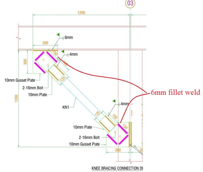
I have attached a figure herewith which will be beneficial in understanding my query.
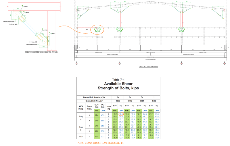
Member_to_carry_a_certain_amount_of_load_only_py1fvk.png


As you can see, the steel building is three-storied, and some knee braces were added previously to avoid retrofitting of some main steel beams (girders). The purpose was to reduce the length of the member and produce less loads in the girder, which was achieved well.

However, the knee braces' connections are not capable to resist the loads transferred to them in ETABS.
Two bolts can carry about 24.8 kips of shear load.

Whereas in FEM (ETABS) we get a force of about 45 kips due to gravity load combos. Also in some gravity+lateral load combos, the applied load exceeds the capacity of the connection.

Is there any method by which we can declare that these knee braces are provided just to carry say 20 kips forces and the latter forces are not intended for it, equilibrium will be established for the whole structure considering this trade-off (knee braces taking only 20 kips).

Is this justifiable??

This is an existing building, we don't want to apply weld and ignore those bolts to carry the applied loads, because it will be massive work and the factory is in operation.

Thanks....
 
Replies continue below

Recommended for you

From that picture it looks like the beam is part of a moment frame with some fixity in the beam - was the beam modeled as fixed ends with the brace way or as a pin connected?

As others stated ignore dead load for what was there before the retrofit and go from that point - superimposed dead plus live, lateral loads, etc.
 
You can declare the load to be whatever you like but that doesn't mean the structure (and physics) will agree with your declaration.

The way to reduce the load to the connection, is provide additional support of the girder to satisfy equilibrium and reduce the load on that support. Full stop.

If you need the knee brace for strength of the girder, then the connection of the knee brace is critical.

IF the connection fails due to bolt shear rupture, then you have no more knee brace and the girder is spanning the full distance between the columns.

Since its not a ductile element you get instant failure and zero load supported by the knee brace, not 20kips, zero.
And besides, even if you can show the bolt ductility in shear, is this really a failure you want under live loading?

No amount of wishful thinking, or declaring, or mental gymnastics changes this reality.

I don't understand why anyone here is even entertaining the idea that you can somehow have a lower load in this member.

The only path I can see to analytically reduce the load on this connection is Live Load Reduciton.


Those welded on plates that the brace is bolted to look very prone to buckling. The plates should have had flanges.
 
this looks like a "band aid" (not meant to be negative). I wonder if the original frame was "inadequate" and the designers added this knee brace to carry the extra load ?
What is the moment capacity of the beam and knee brace together ? The failure mode of the knee brace (fastener shear ?) is troubling (as it is quite a "brittle" failure). If the fasteners were limited in bearing, that'd be better.

if this is forensic engineering, then I think you can say "not sufficient for the current requirements".

Can you access the fasteners (the wall behind looks close) ?

"Hoffen wir mal, dass alles gut geht !"
General Paulus, Nov 1942, outside Stalingrad after the launch of Operation Uranus.
 
You could model the connections in Idea Statica to obtain the stiffness of the connections. Once you have the stiffness values you can use modifiers at your frame connections to determine a more reasonable estimate of the brace force. I see a lot of brick in the image as well. How is connected and is there more blockwork?
 
SWC has a point ... maybe the plates buckle before the fasteners shear ?

"Hoffen wir mal, dass alles gut geht !"
General Paulus, Nov 1942, outside Stalingrad after the launch of Operation Uranus.
 
rb1957 said:
SWC has a point ... maybe the plates buckle before the fasteners shear ?
Yeah, this could be limit state.
So, I should determine stiffness of the connection in IDEA Statica and model it to capture the buckling issues etc. And then use this stiffness in FEM to get final result.
 
To me that looks like a large sized beam and a small sized knee brace.
I'd be curious what the behavior of the beam is without the knee braces and how much the knee brace analysis helped.
If the designer thought that those small knee braces reduced the effective length of that large beam, I think he/she is drinking too much coolaid.
 
rb1957 said:
Can you access the fasteners (the wall behind looks close) ?
Not this one. But a lot of these braces exist in this structure.
 
IFRS said:
I'd be curious what the behavior of the beam is without the knee braces and how much the knee brace analysis helped.
If the designer thought that those small knee braces reduced the effective length of that large beam, I think he/she is drinking too much coolaid.

But beam end moments decrease which help it to be adequate.
 
Any chance you can take advantage of live load reduction?
 
if you do limit these to 20 kips, how much margin do you have in the beam ?

what is the allowable load in the plates (buckling) ? if <20 kip then good (this limits the load in the brace), but the beam'll take more load ... sufficient margin ??
If more than 20kip, what would it take to get it down to < 20 kip ? Can you reduce the size of the plates, in situ ?

"Hoffen wir mal, dass alles gut geht !"
General Paulus, Nov 1942, outside Stalingrad after the launch of Operation Uranus.
 
PMR said:
Any chance you can take advantage of live load reduction?
Yes, I can use LLR to reduce some loads on the brace, but it won't solve the problem as a whole.

rb1957 said:
what is the allowable load in the plates (buckling) ? if <20 kip then good (this limits the load in the brace), but the beam'll take more load ... sufficient margin ??
I didn't check buckling of the plates. But I checked the girders considering brace force less than or about 20 kips. The beams were good.

If more than 20kip, what would it take to get it down to < 20 kip ? Can you reduce the size of the plates, in situ ?
It's probably not a feasible solution for this specific case. Client doesn't want production hamper.
 
45 kips vs 20 kips for gravity loading is a severe difference. If the analysis is correct, it suggests that the brace connection completely fails at less than half the design loading. After the conneciton fails you don't get 20 kips in your brace anymore, you get zero.

If the girder can span the design loads without the brace maybe this is okay. But if the girder needs the knee braces to meet code requirements then there is no way this works.
 
It has been a long time since I did any structural work, but here is my $0.02.
My first thought is to remove the existing braces and replace them with a piece of channel.
Weld along the sides to the existing plates.
Make sure that there is enough weld to get the connection strength, and that the gaps at the ends are short enough to eliminate buckling concerns.
These look like easy welds and they could be done one at a time.
Would that get you where you need to be?

= = = = = = = = = = = = = = = = = = = =
P.E. Metallurgy, consulting work welcomed
 
driftLimiter said:
But if the girder needs the knee braces to meet code requirements then there is no way this works.
Wouldn't you consider in this case that the gravity dead loads have been already supported by the girder, the knee brace had been added recently without jacking the girder up. So, it may be said that the knee braces are added at girder's deformed shape for dead load, hence some load amounting to service dead load may be deducted from the total load. Secondly, live load reduction has some good effect.
 
EdStainless said:
My first thought is to remove the existing braces and replace them with a piece of channel.
Weld along the sides to the existing plates.
Make sure that there is enough weld to get the connection strength, and that the gaps at the ends are short enough to eliminate buckling concerns.

Yeah, that's good to do. However, if it were possible then it could be done a lot easier than replacing the material as follows.

The_2-16mm_bolt_connection_and_a_probable_solution_l0bjhj.jpg
 
I would agree with both live load reduction, and accounting that the brace was installed while dead load was applied.
But, if the 1.6LL is still greater than the connection capacity then there is a problem.
 
Just for clarification, if I check for 1.2DL+1.6LL load combo as an example, then do I deduct 1.0 DL or 1.2 DL??
 
but that's "simply" saying the brace isn't good enough, and adding structure to make it good. possibly the point of this thread is to discuss the options, and now you've arrived at a reasonable (IMHO) conclusion.

"Hoffen wir mal, dass alles gut geht !"
General Paulus, Nov 1942, outside Stalingrad after the launch of Operation Uranus.
 
Status
Not open for further replies.

Part and Inventory Search

Sponsor