Eng-Tips is the largest engineering community on the Internet

Intelligent Work Forums for Engineering Professionals

Declaring steel knee brace to take only 20 kips axial load as bolt capacity inadequate 11

Status
Not open for further replies.

NewbieInSE

Structural
Dec 19, 2019
234
0
0
BD
Dear Engineers,

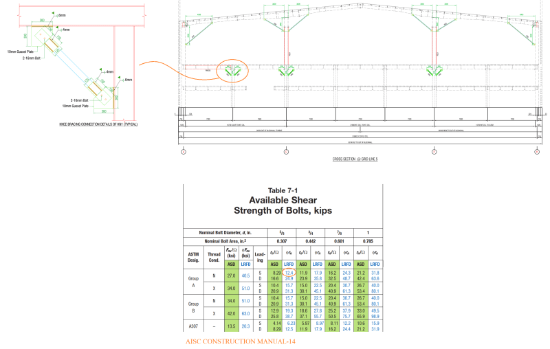
I have attached a figure herewith which will be beneficial in understanding my query.
Member_to_carry_a_certain_amount_of_load_only_py1fvk.png


As you can see, the steel building is three-storied, and some knee braces were added previously to avoid retrofitting of some main steel beams (girders). The purpose was to reduce the length of the member and produce less loads in the girder, which was achieved well.

However, the knee braces' connections are not capable to resist the loads transferred to them in ETABS.
Two bolts can carry about 24.8 kips of shear load.

Whereas in FEM (ETABS) we get a force of about 45 kips due to gravity load combos. Also in some gravity+lateral load combos, the applied load exceeds the capacity of the connection.

Is there any method by which we can declare that these knee braces are provided just to carry say 20 kips forces and the latter forces are not intended for it, equilibrium will be established for the whole structure considering this trade-off (knee braces taking only 20 kips).

Is this justifiable??

This is an existing building, we don't want to apply weld and ignore those bolts to carry the applied loads, because it will be massive work and the factory is in operation.

Thanks....
 
Replies continue below

Recommended for you

That's a situation, rb1957. I know it is very disturbing to emphasize on the fact that we do not want to try for any change.
Without changing the connection, do you have any easier way out?
I think I would check buckling and other stuffs and find stiffness of the connection and assign it in the model to attract loads suitably.
From this obtained load, i would deduct the dead load, on LL apply LLRF and finally calculate the load and check against connection capacity.
 
no, all quite reasonable (particularly for a "newbie"). Agreed, no one wants to change something already built that seems to be working well enough (but possibly not to code). Agreed, we try analysis solutions. and you (as a newbie) need help (and presumably there's no one close to mentor you) and you've reached out.

I hope we helped you realise the best way forward (whether the client likes it or not).

"Hoffen wir mal, dass alles gut geht !"
General Paulus, Nov 1942, outside Stalingrad after the launch of Operation Uranus.
 
What is the moment in the beam with and without the brace?
Have you found the deflection of the beam without the brace at the location of the brace?
What happens if one side of the column is experiencing full live loads and the other is not?
 
driftLimiter said:
No amount of wishful thinking, or declaring, or mental gymnastics changes this reality.

I don't understand why anyone here is even entertaining the idea that you can somehow have a lower load in this member.
Pretty much this. Though there is a possibility to "declare" a load if you are clever about it, but you need to tread damn carefully because you are essentially assuming some yielding.

Sure once you go deeper we do in fact 'declare' loads in some circumstances. This comes about with multiple load paths and implicit but often unstated assumptions that there is suitable elastic/plastic deformation to allow this. A simple example is assuming all bolts in a bolt line share the shear load. The reality could be that one bolt or two takes it all on light loads, this is a simply down to fabrication tolerances. But a round bolt in a large round hole is a point load and elastic or plastic yielding is inevitable and load sharing occurs.

You can approach a problem like this and declare a load. But then you need to back calculate the behaviour of the system under your declared load to ensure it doesn't fail under the resultant strain.

In this example it is a relatively simple to back calculate the required deflection that the beam must undergo to limit the load on the knee brace to 20kips. If that deflection is 0.1mm (unlikely) you are going to be fine.

If the calculated deflection is beyond the plastic or buckling STRAIN limit of the connection then the connection would be expected to fail.
 
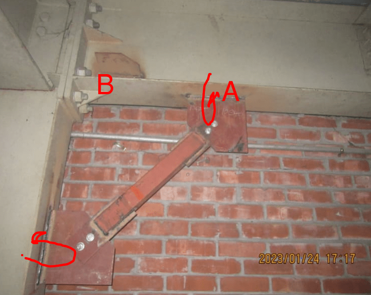
It looks like in the photo that you could weld the plate to the gusset, thereby no longer requiring the bolts. Is there a reason welds can't be added to remove the bolts being the failure mechanism?
 
Do you know what the original design intention was?

This is the sort of retrofit detail where I can see someone doing an analysis and:

1. Seeing a moment overage, and designing for that without seeing the vertical load path
2. Seeing a need for lateral capacity and not seeing the vertical load path
3. Seeing an overage and designing for the overage only without evaluating the stiffness change or realizing that load sharing doesn't necessarily work like that

That being said, depending on the stiffnesses of things, there might be some argument that the relative stiffnesses will bias loads away from the brace.

1. As discussed, the dead load was already applied
2. The stiffness of the already loaded moment connection is going to be higher than the brace. It needs to move to take up the bolt hole slop before it even starts to load. That close to the support point, this amount of movement actually may be a reasonable amount of load

That being said, it seems like this reinforcement won't do much until you get pretty high up on the stress range for the structure. So I suspect you can't say much about proving it with existing service history.

You can make lots of judgements, but I question how solidly you'll feel relying on them given the fact that you can't rely on load history very much.

The easiest thing to do would be to slip bolts out one at a time and replace them with stronger bolts. But knowing the behaviour when you take one bolt out is going to be tricky given how badly the numbers do just based on gravity, so I'm not sure that's even a good idea.

I think you weld it and call it a day.
 
Excellent point TLHS. I'm not sure if anybody else mentioned the same thing but recognising this and understanding this is pretty damn important. The output from the structural package will be well off.

Working out what loads will go where here is very difficult because you have two stiff relatively stiff (low deflection) connections but one with bolt hole slop and hole yielding that needs to be taken up first before it really sees load. We might only be talking 1.5mm here but that 1.5mm is probably a very large deflection for that moment connected beam.

I've recently had a retrofit involving placing struts under an existing beam. However in my situation the deflection at ULS was 25mm+. So more than enough to take up the initial slop in installation of the new members. (I had hoped to preload the new members but in practice this was too challenging and not needed.)
 
Thanks TLHS & Human.

TLHS, your load path discussion was enlightening for me, thanks. The original intention of putting the brace below was to lower bending demand in the rigidly connected beam.

Anyway, I think I'll go for welding.
 
NewbieInSE said:
TLHS, your load path discussion was enlightening for me, thanks. The original intention of putting the brace below was to lower bending demand in the rigidly connected beam.

If that was the intention it probably never worked as intended!

If you are going to go with welding you can reasonable assume that any increase in load (EG imposed load) will be distributed between the beam connection and the strut in accordance with their relative stiffness's. A good portion if no all the existing dead load is probably just on the beam and its connection. This calculation starts to get somewhat convoluted quickly, just be thankful things are largely additive and linear!

(Whereas a bolted connection displays significant non linear behaviour when it comes to load sharing because of the slop and bedding in.)

You can quickly test to see if the struts are carrying load by simply removing the nuts off the bolts and see if the strut will readily come loose!


Oh and on the other side of the retrofit fence. Today I quickly finished off a design to support a load that was suppose to be supported by another load path but the capacity of that load path is insufficient due to a project manager screw up. (Long story.) The other load path is good for maybe 50%-75% of the expected load, or even 100% but I'm not going to play the casino here.

So screw load sharing. I've designed addition supports that are good for 150% of the ULS load. Both slop and stretch exist in both connections so decent ductility. So the additional support will take as 'as much load as is necessary'. I could not begin to quantify how much actual load that the additional supports will end up bearing! Things get rapidly complicated when there are multiple load paths.
 
Human909, if i calculate connection stiffness of the beam and knee brace, then assign them in FEM. There is a possibility of getting lower forces in the braces, right? Let's ignore how much loaded the beam is already due to dead weight. I ran some analysis without the effects of those knee braces, and at most of the locations the beams look good for bending, but at a few they are inadequate. I think the braces just being able to take some little axial loads will reduce bending in beam just enough to be adequate.
 
Moment is additive. So;
if you calculate the moment in the beam due to dead weight before the brace(assuming the brace was installed with no live load),
and then calculated the moment in the beam and due to imposed loads etc in the presences of the brace,
and then add them together and including relevant factors then you'll be getting somewhere

If this moment does not exceed the capacity well you might just be OK.

 
Unless I'm mistaken, the knee brace member here is flat strap. Granted, I do have pretty serious presbyopia these days. If that's correct, then I would offer the following, dissenting opinion:

1) No way in hell these were ever installed with the intent of assisting the girders.

2) I highly suspect that the knee braces were intended to serve as tension only, lateral load resisting elements.

3) Ideally, the flat strap would buckle out of the way before the overloading the bolts in compression (gravity or lateral induced).

To the extent that I'm correct about this, you may well be able to cap the amount of force received by the bolts well below that which would be predicted by your ETABS model.

 
This is an imperfect analog but, conceptually, tension only knee bracing is a bit like Flexible Moment Connections which are also intended to meaningfully engage only under the action of lateral loads: Link.

Frankly, I detest both knee braces and FMC and try mightily hard to avoid both in the context of new builds. But, alas, I'm not the boss of the world so this stuff must be accommodated sometimes. I table this simply to point out that there is precedent for such things.

Clearly, the bolts have not been overloaded by beam shear yet. That's something, particularly given that prying action from the girder would develop monstrous forces in an unbuckled brace in a wicked hurry.
 
TLHS said:
Koot, I'm pretty sure those are square HSS with a knife plate.

There's definitely some thickness there. I'd considered either:

1) Two straps with a spacer to facilitate symmetry.

2) A rather narrow HSS.

Either way, the same thing may apply. Granted, even a narrow HSS will have significant axial capacity over such a short length.
 
Additional observations:

1) The girder to column connection here is obviously a moment connection of some stiffness. So point is a location of minimal beam slope. That, as opposed to it being a point of maximal beam slope as would be the case for a simply supported beam.

2) The brace only absorbs connection in proportion to how much point [A] moves downward. Given the scale of the girder, and the presence of the moment connection, I'm guess that deformation is pretty small.

3) Given the scale of the girder to column moment connection, it's hard to imagine that the braces would do anything meaningful for lateral loads, even if they were adequately designed for the anticipated compression.

4) The brace gussets are horribly eccentric. My money would be on them rolling over long before the brace was fully mobilized for anything usefull in compression.

SUMMARY: I'd be treating this connection as though the brace wasn't even there.

C01_ceeek3.png
 
Status
Not open for further replies.
Back
Top