Eng-Tips is the largest engineering community on the Internet

Intelligent Work Forums for Engineering Professionals

Deep Excavation - AMA 1

Status
Not open for further replies.

JSD1986

Structural
May 2, 2012
25
0
0
AU
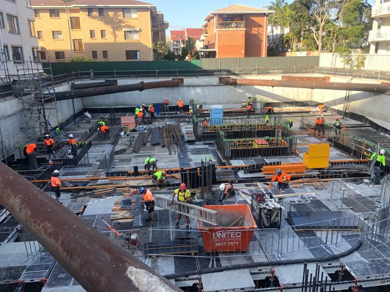
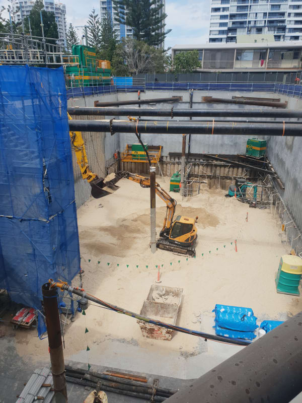
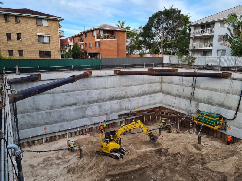
Deep Excavation - 13m cut. Approx 8m below water table.

Any quesrions.

bigdog_axgtdy.jpg
 
Replies continue below

Recommended for you

Yes you came just in time :D 
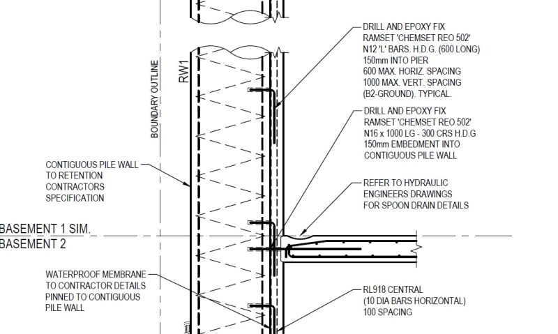
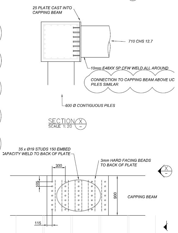
. So this a slurry wall founded on secant metallic piles right ? and how do you go by connecting the underground floor slabs to the retaining wall ? thank you
 
PEinc - The pile installation was underway when the client advised that a hydraulic tank in the corner was required. This made the excavation approx 1.5m deeper which made the pile reo and length insufficient. This extra brace was installed to solve this problem.

killswitchengage - they are 600mm diameter CFA contiguous piles (no interlock). The restraint is provided by internal braces connected to a RC capping beam. The shotcrete you can see at this stage just prevents soil migrating between the small 40mm gaps between the piles during excavation. Eventually a thicker RC shotcrete (finished) wall will be connected to the piles. The raft and slabs will also be dowelled into the piles. Ground water is controlled by a series of deep wells which are approx. 6m below the underside of the raft.


A few days ago:


b_lncmgi.jpg


Raft and one suspended slab in place. Photo shows second suspended slab being built. Once this slab is poured and up to suitable strength the big steel braces will be removed to provide unimpeded construction.
 
Can you please give the detailed drawing on the slab connection to the piles ? also i wanna know how these hydraulic jacks are designed especially the ones in the corner if possible
 
PEinc - The deep wells are designed in such a way that the 'draw down curve' is below the excavation and removes hydrostatic pressure from the wall. There were also spears installed from the lower level as the wells didn't quite do the job.

c_iba7ug.jpg


killswitchengage - The slab dowels into the piles as such.

d_nej9yt.jpg


The struts are 710 CHS 12.7. They are welded to a plate that was cast into capping beam. The plate had a series of shear studs. To design the struts I essentially determined the load in the strut and determined the capacity with regards to buckling. The struts were approx 20m long and had about 4000kN.

e_uajftm.jpg


Retrograde - Project is on the Gold Coast - Australia.
 
When I workout the shear load being transferred into the capping beam I need to be able to justify that not all the load goes through the shear studs - that some occurs with friction between the plate and the concrete. Adding some hard faced beads gives me a little more confidence that this will occur. (not the most scientific approach really - In our game it pays to be a little superstitious)
 
That is not a mechanism I would rely on. The shear studs require a certain amount of slip to occur before they reach their full capacity; however, load transfer by friction between the plate and the concrete assumes no slip. At least that is my understanding.

Also, with strut design you need to ensure you account for the bending moment in the strut due to self weight. I normally also increase this moment due to the P-Delta effect caused by sag in the strut.
 
The capping beam is poured with the shear plate in place so i'm fairly confident there is a fair amount of load being taken up via skin friction between the plate and the RC beam.

The strut is designed for this sag. Without considering these second order effects the 710 CHS is good for about 8700kN. Once we take into account the strut length its only good for about 5500kN and this is ignoring the fact the end is cast in and a pretty good moment connection and thus reduces the effective length.

Another similar project for good measure.

20190123_093004_l2dnhk.jpg
 
I don't have much to say about the excavation, contiguous piles, and struts. But in my opinion, the support of the slabs on the wall is a bit tenuous.
 
N16 at 300 cntrs good for about 110kn/m ULT in pure shear which ignores the fact its notched to some degree into the shotcrete wall. Column row typically about 8m off the shoring wall. Say 20kpa ultimate UDL with 4m load wide = 80kn/m shear load at the pile interface.

On first glance this passes the sniff test to me. What stands out to you as tenuous?
 
If I remember correctly, Hokie is not a fan of relying essentially on shear friction (dowel action) for any serious shear loads.

Neither are lots of us to be honest, but if there's a bit of a key in the shotcrete then I'd likely be ok with it.
 
Even if I did support shear friction theory, this is not it, as the bars are not developed into the piles. I wonder how you arrived at 33 kN per N16 dowel. Dowel action has very little to do with the strength of the bar, but rather bearing in the concrete, and that methodology is not well codified. Like jayrod12, if there is enough key depth, I would be happy, but 50 mm would be my minimum, and it doesn't look like you have that much. The spoon drain is also worrisome, as hydraulic engineers and concrete finishers can create havoc with your depth.
 
Im not sure what country you're based in but in Australia there is a technical specification which covers this exact type of situation. Standards Australia SA TS 101:2015 - Design of post-installed and cast in fastenings for use in concrete.

I'm not suggesting there aren't potential design flaws with the concept but the approach is adopted by smaller structural firms as well as the publicly traded firms.

From a pure engineering standpoint the connection type has some capacity which can be evaluated which means applying LRFD philosophy has to apply to at least some degree.
 
Status
Not open for further replies.
Back
Top