Eng-Tips is the largest engineering community on the Internet

Intelligent Work Forums for Engineering Professionals

Deflection Criteria for Industrial Utility Racks Supported from Roof of PEMB

Status
Not open for further replies.

thoughtofthis

Structural
Jan 16, 2012
31
0
0
US
In my experience, utility racks are typically designed using a deflection ratio of L/240 for beams between supports using the collateral + operating load. This can vary based on what's being conveyed in the pipes and to address specific loading conditions (e.g. - if the pipe rack is outside, you might consider snow/ice, etc). This assumes pipe racks are free standing.

However, if the racks are hung from the roof of a structure, the deflections can be additive. A PEMB rafter may deflect L/180 under a collateral + roof live/snow condition.

For example, a 8' wide rack with hangers every 25 ft @ L/240 deflects 1.25" (25'*12"/'/240, girder) + 0.4" (8'*12"/'/240, cross-beam). The rack is parallel to a rafter spanning 75' @ L/180, so the rafter deflection is 5" at mid-span (75'*12"/'/180). Assuming a hanger at mid-span of the rafter, a pipe on the center of the rack could deflect 6.65" or L/135 @ 75'. In this situation, to maintain L/240 at the rack, the deflection limits of the rack and the building would need to be increased.

This example is greatly simplified, but highlights the issue. There could be dozens of scenarios that need to be addressed in a single building. In addition, when designing the rack in a PEMB, you might not have the actual rafter stiffness or deflection until after everything is designed (at best) or never (depending on the vendor). Are there any standards, guidelines or references that cover this?
 
Replies continue below

Recommended for you

Apart from good engineering practice, I'm not sure of a codified requirement. In the US, serviceability is mostly left up to the engineer. There are some basics for gravity loads, but lateral deflection requirements, deflections of structures supporting sensitive equipment or systems, vibrations, etc. are not mandated anywhere unless the engineer mandates them in his or her design.

If you're the EOR on the project from the beginning, you can set requirements for the PEMB supplier. They certainly won't like it. The low bidder will probably try to slip a non-compliant design past you in review (which may or may not be intentional, since I've had a few that claimed to not know there were structural drawings in the bid set). But you can tell them that purlins at locations a, b, and c must support an additional load of x kips with a deflection limit of y inches.

When I'm brought into a project after the fact - the PEMB is already designed and they want me to design the 'extra stuff'...first I think really hard about whether or not I want to deal with the headache, and then I tell them that if I do it nothing will be attached to the PEMB because it probably won't be able to support anything but hanging some lights, fans, and duct work if it wasn't designed for it from the start.
 
Assuming a hanger at mid-span of the rafter, a pipe on the center of the rack could deflect 6.65" or L/135 @ 75'. In this situation, to maintain L/240 at the rack, the deflection limits of the rack and the building would need to be increased.

I think you are conflating deflection and displacement. Deflection limits are traditionally based on individual member spans and are meant to provide a minimum member stiffness as good practice based on experience. Cumulative total displacement of an entire structural system is a different animal.
 
The L/135 mentioned above was just to provide a relative comparison to the L/240 deflection limits I'm used to seeing for girders/beams on utility racks. I did not mean to imply that there was a deflection limit for the combined system. However, I do think the total displacement of the system is relevant to the design of the utilities.
 
I think that's just an inherent design parameter in the nature of all buildings and structures. Everything has a limit to which it can displace before it bonks into something or something stops functioning correctly (like a doors, facade systems, utilities with no flex connections, etc). It's impossible to codify that because there are infinite possible scenarios that have to be evaluated on a case by case basis.
 
Your question in the OP is confusing.
thoughtofthis said:
In addition, when designing the rack in a PEMB, you might not have the actual rafter stiffness or deflection
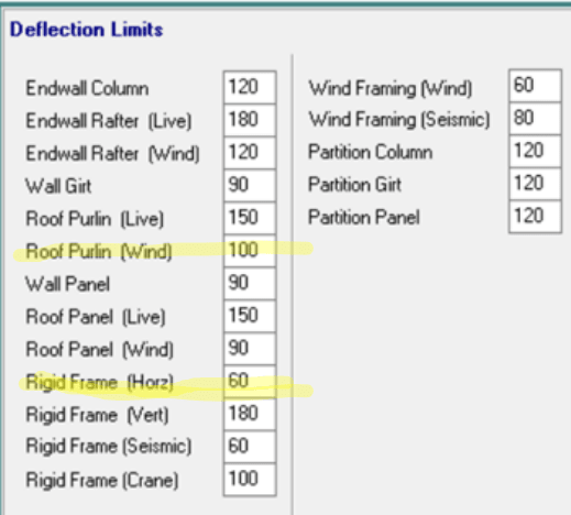
Are you asking about the deflection criteria that PEMBs use? They usually follow the MBMA manual and you could ask the PEMB who is supplying your building. Here is what one PEMB gave but you could specify a tighter criteria if needed.

Screenshot_ynwaie.png
 
Chapter 3 (Serviceability) of the MBMA - Metal Building Systems Manual might provide some additional insight on the standard deflections that PEMB manufacturers use, and you should be able to find the 2012 or 2018 version online somewhere. GC_Hopi's deflection limits are similar to what my company uses for their design. That screen is from MBS (Metal Building Software), which is the standard software for most PEMB manufacturers.
 
Status
Not open for further replies.
Back
Top