Hey all,
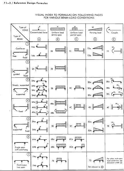
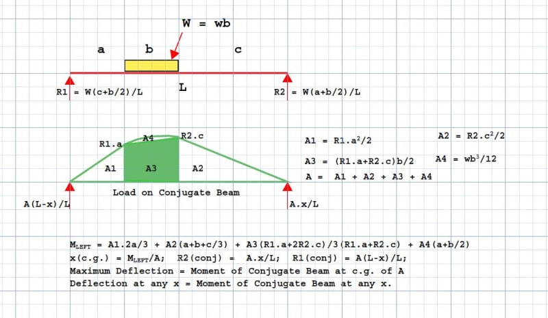
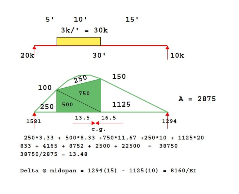
Anyone know of a resource to find a ton of different deflection equations? Everything I can find for a UDL not across the whole beam (and not located starting at a support) only gives the moment equation and no deflection.
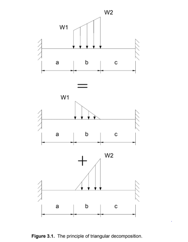
Or if you know of a good resource where they go over the derivation of the deflection equations. For weird cases I typically use clearcalcs or RISA 2D for quick results, but it would be nice to have a spreadsheet that uses the superimpose method.
Anyone know of a resource to find a ton of different deflection equations? Everything I can find for a UDL not across the whole beam (and not located starting at a support) only gives the moment equation and no deflection.
Or if you know of a good resource where they go over the derivation of the deflection equations. For weird cases I typically use clearcalcs or RISA 2D for quick results, but it would be nice to have a spreadsheet that uses the superimpose method.

")