Eng-Tips is the largest engineering community on the Internet

Intelligent Work Forums for Engineering Professionals

  • Congratulations waross on being selected by the Tek-Tips community for having the most helpful posts in the forums last week. Way to Go!

Deflection Equations 2

Status
Not open for further replies.

EngDM

Structural
Aug 10, 2021
367
1
18
CA
Hey all,

Anyone know of a resource to find a ton of different deflection equations? Everything I can find for a UDL not across the whole beam (and not located starting at a support) only gives the moment equation and no deflection.

Or if you know of a good resource where they go over the derivation of the deflection equations. For weird cases I typically use clearcalcs or RISA 2D for quick results, but it would be nice to have a spreadsheet that uses the superimpose method.
 
Replies continue below

Recommended for you

Thanks Doug, I will look forward to see your results. I have just recently heard of the Macauley method of calculating deflections. At first I didn't think it was any different than the double integration method which we learned back in the early 1950's, but it seems there are a couple of new wrinkles which I am not familiar with yet. I'm looking forward to studying it a bit more.
 
For BAretired's beam:

I set EI to 8160 and got identical results with the spreadsheet and FEA analysis:

With the distributed load: deflection at mid-span = 1.685, maximum moment = 166.7 kip ft.

With the point load at 10 ft: deflection at mid-span = 1.762, maximum moment = 200 kip ft.

Doug Jenkins
Interactive Design Services
 
Something is wrong Doug. My last line should read: Delta @ midspan = 1294(15) - 1125(5) = 13,785/EI, not 8160/EI.

I agree with your maximum moments of 167'k and 200'k for the distributed and point load cases respectively, but the deflections can't be right, particularly if they are in feet.

For a maximum moment of 200'k, we could try W18x50 with I of 802in^4. EI=29,000k/in^2*802in^4 = 23.258e6 k-in^2 or 161,514 k-ft^2. Then delta = 13785/161,514 = 0.08535' = 1.02", very nearly L/360, which sounds a little more reasonable.
 
BAretired said:
Something is wrong Doug. My last line should read: Delta @ midspan = 1294(15) - 1125(5) = 13,785/EI, not 8160/EI.

I set the EI to 8160 so the deflection would be 1 foot. Changing to 13,785 I get:
- At mid-span 0.997 ft
= At 13.923 ft (max. deflection point): 1.004 ft.

So that's pretty good :)

Using your realistic EI value I get a maximum deflection of 1.028 in.

By the way the units-aware version of my spreadsheet is very sensitive to the format of non-SI units, and it doesn't give a helpful message if it doesn't like the units, so I'm working on making it friendlier. I will post here when I have finished.

For now, units that work are:
EI: kipf.ft2
Load/m: kipf/ft
Moment: kip ft or kip in

(so EI needs a . between the units, but for moment it has to be a space)


Doug Jenkins
Interactive Design Services
 
BAretired said:
In most cases, finding deflection is an exercise to meet code requirements after having already selected a beam which has adequate strength. Often, the deflections are not a problem. When that is the case, there is no point in wasting design time performing useless work.

Interesting. 75% of all beams I size are deflection limited. This is residential and light commercial though. So much so, that I check deflection first on most beams.
 
Do you select a minimum depth of L/20 in the case of a steel beam? If you do, deflection will not be such a common problem. Checking deflection first is definitely ass backwards.


BAretired said:
Checking deflection first is definitely ass backwards.

Uh, yeah, NO


Honestly, I can count on the one hand the number of times strength controlled an LVL or steel beam in residential or light commercial so I might as well check deflection first.Bearing stress is the next thing I check for wood construction.
 
If that is the case, how do you solve for beam deflections in complicated loading patterns such as described by the OP in this thread, or do you rely entirely on computer programs?
 
I typically make simplifying assumptions or I use a beam program. Unless I am trying to design to the gnats ass, it is usually good enough. I have done enough beams by hand and then checked them with software that I have a pretty good idea of how i can simplify loadings.
 
Good answer, XR 250. I did something similar when I was practicing, except there wasn't such a wide choice of software in those days to check hand calculations. I'd like to look further into the Macauley Method just for fun. At first glance, it seems to be a simplification of hand calcs.
 
I use a beam program and ballpark it with a simplified loading scenario that's covered in the DA6 document or the tables. Meets my needs, I understand the Fermi problems of the results, and still can keep trucking with production work. It would be interesting to know what the OP's original design situation.
 
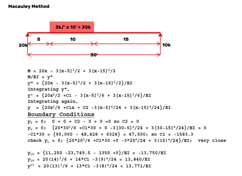
The same patch loading solved earlier using Conjugate Beam is solved below using the Macauley Method. It looks like a good way to find deflection when there are many different load types and it should be ideal for a spreadsheet.

The location of maximum deflection could have been solved by setting y' equal to zero, but it would require solving a cubic equation, so deflections were found at three locations. Maximum deflection is seen to be located between 13' and 15' from the left end.

Capture_dwtfzn.jpg
 
Full general derivations via direct integration for Concentrated Moment, Point Load, and linear varying distributed load can be found here: Link

These are derived using a consistent sign convention of positive loading and reactions pointing in the positive y direction, positive moments are counter-clockwise, and positive internal shear points in the negative y direction. This results in beam rotations and deflections consistent with common practice. The derivations assume consistent units across the various inputs. Fixed end moment formulas are also included.
 
Status
Not open for further replies.
Back
Top