Eng-Tips is the largest engineering community on the Internet

Intelligent Work Forums for Engineering Professionals

  • Congratulations waross on being selected by the Tek-Tips community for having the most helpful posts in the forums last week. Way to Go!

Deflection Formulas

Status
Not open for further replies.

jjalex1

Structural
Jan 3, 2012
22
0
0
US
Does anyone know what's the deflection formula for a beam overhang one support for a triangular distributed load over the entire beam? Beam is supported by two supports.

 
Replies continue below

Recommended for you

You could superimpose two load cases, one with triangular loading and simply supported at ends, and one simply supported with concentrated load at arbitrary point, to get the total deflection.
 
Capture_ce0s2m.jpg


By superposition you can combine the above, note the trapezoidal load can be pulled from an AISC steel manual as a superposition of a triangular load and uniform load. The rotation will be the derivative of the deflection formulas provided in the AISC manual, should be inclusive of the rotation created by the applied moment.

Open Source Structural Applications:
 
principle of superposition can still be applied. You'd have 5 more sub-sets in addition to original ones I have shown:
left cantilever as free-fixed with triangular load
left cantilever as free-fixed with uniform load (assuming a triangular load peak at left and 0 at end of the right cantilever you will have a trapezoidal load on the left cantilever and center span)
center beam with left cantilever triangular load moment reaction at left end
center beam with left cantilever uniform load moment reaction at left end
left overhang with rotation from center span considering all loads applied to the center span

Open Source Structural Applications:
 
@BAretired:
yep can be there are certainly other better/faster methods - finite element, bracket functions, simple hand plots and area under the curve, direct integration, etc.
heck if you can come up with the loading equation you can throw it on Wolfram-Alpha and get the general form equations.

Op can certainly use a spreadsheet/program to find the answer but always good to be able to break it down to simpler problems that can be easily hand calc'ed to provide verification of the computer result or get yourself in the ballpark.


Open Source Structural Applications:
 
Depending on the gradient of the load triangle, I'd probably simplify it to a UDL + an equivalent point load acting at the centre of the triangle and superimpose the effects.

I would basically always analyse this with a FEA program like LUSAS and do a quick back of fag packet hand calc, although I appreciate not everyone has access to software.


Edit: For deflection would definitely use a 2D beam model here
 
It should just be two load cases superimposed, and both cases should be in the AISC manual or Roark's- calculate the intermediate load to make the reaction at one end go to zero.


Super_mzdezj.jpg
 
Often, when calculating deflection, great precision is not required. Usually, we want to know whether or not deflection complies with the code.

Taking W = (w1+w2)L/2, the maximum deflection is approximately 5WL[sup]3[/sup]/384EI, using the formula for a uniform load. If this satisfies code, there is no need to go further. Otherwise, the effect of a moment at one or both ends can be accommodated with satisfactory precision.
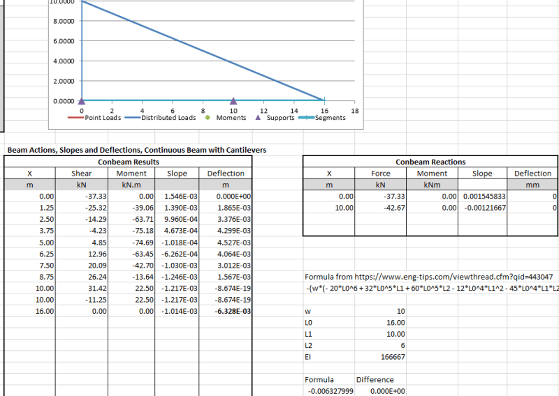
For uniform load, Δ[sub]max[/sub] = 0.01302WL[sup]3[/sup]/EI whereas for a triangular load, Δ[sub]max[/sub] = 0.01304WL[sup]3[/sup]/EI.


BA
 
Sounds like the perfect problem for Macaulay's Method or the Singularity Function method.

For triangular distributed loads the discontinuity loading function is of the form w = m*<x-a>^2, where m is the slope of the distributed load. The same integration rules apply.

Keep em' Flying
//Fight Corrosion!
 
I second Celt83's suggested spreadsheet :)

Also for a quick check, calculate the end slope for a simple span with a uniform load and project that over the length of the cantilever. That's pretty close for a cantilever up to about 1/4 of the main span.


Doug Jenkins
Interactive Design Services
 
Hello

If you have access for AUTOCAD ACAD Mechanical there is a beam program that will do above and more. I can run anything in minutes, if desired.

Or There is a free FEA program called JL Analayzer that has allows beam elements(as I recall). Only 300 nodes. Now I am spoiled with fusion360.

 
From virtual work, the deflection at the tip is:

Delta = -(w*(- 20*L^6 + 32*L^5*L1 + 60*L^5*L2 - 12*L^4*L1^2 - 45*L^4*L1*L2 - 60*L^4*L2^2 + 20*L^3*L2^3 + 10*L^2*L1*L2^3 + 3*L1*L2^5))/(360*EI*L1^2)

where
w = max uniform load at the left end
L1 = backspan length
L2 = overhang length
L = total length = L1 + L2

I checked this using two cases in SAP2000 and it worked.

Please check to make sure you agree before using it.
 
Status
Not open for further replies.
Back
Top