Continue to Site

Eng-Tips is the largest engineering community on the Internet

Intelligent Work Forums for Engineering Professionals

  • Congratulations GregLocock on being selected by the Eng-Tips community for having the most helpful posts in the forums last week. Way to Go!

Deflection in a 12" sch 40 pipe (with internal pipe supports) problem 2

Status
Not open for further replies.

BILL486

Mechanical
Mar 30, 2004
2
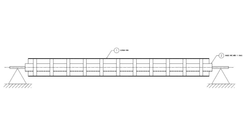
I have to find out deflection in a 12" pipe with fixed bearing supports at both ends. However, the ID of this pipe has an internal smaller pipe with equally spaced 1" wide rings (donuts) plug welded in place for better support internally. My question is, how do I calculate deflection of the entire assy? Would I have to neglect the welds?

Thanks,
Bill H.
 
Replies continue below

Recommended for you

If the welding is sufficient, you may have the two pipes working together, in which a larger I would be warranted. You would have to do a shear flow analysis.

Do you have a model of what you describe that you can post?

Mike McCann, PE, SE (WA)


Are the internal centering rings tight to both pipes?
If not then they don't matter.
By the same token if they are far apart they may not add a significant amount of stiffness either.

= = = = = = = = = = = = = = = = = = = =
P.E. Metallurgy, Plymouth Tube
 
BILL486 said:
My question is, how do I calculate deflection of the entire assy? Would I have to neglect the welds?

Before making a judgement call on the effect of the internals, find deflection upper and lower bounds:

1) Calculate defection ignoring the internals.

2) Calculate defection assuming the internals contribute 100%.

If the internal pipe is "small" (giving it a relatively low moment of inertia) compared to the 12" pipe, upper and lower deflection bounds will probably be surprising close together... making the judgement call much easier or not even necessary.

[idea]
 
I like SRE's advice on the upper/lower bound check - I find myself sweating over decisions sometimes and once you run the numbers you realize there wasn't much a choice to make anyway.

Aside from that - if the pipes are centered on each other, there is no shear flow - Q = 0 and then so does VQ/IT. In that case, the composite section would have the same stiffness as the non-composite section. I believe there was a fairly extensive thread on this topic a few months back.
 
Attached is a diagram of the question.

12_deflection_pipe_lxwd6y.jpg
 
Yeah, add the stiffness of the inner and outer tubes but expect the outer tube's contribution to domiinate.

 
Can I ask what this installation is trying to accomplish?
 
I would only consider the outer pipe. I don't think those "donuts" will be able to transfer the horizontal shear required for the section to act compositely unless they are very thick or stiffened.

In any case, the major contribution to resistance would have come from the outer pipe, anyways.
 
Michael Chen said:
I don't think those "donuts" will be able to transfer the horizontal shear required for the section to act compositely

Both individual pipes and the composite section all share the same centroid - shear flow is zero.
 
Not sure how big the inner pipe is, but a 12" pipe has an I=262 in^4 and for example if the inner pipe is 4" its I=6.82 in^4. If it is a composite section it is not really much bang for your buck. The two pipes are concentric, so the combined I is just the sum of the two individual I's.

I would probably just look at the outer pipe and be done with it.
 
Status
Not open for further replies.

Part and Inventory Search

Sponsor