Continue to Site

Eng-Tips is the largest engineering community on the Internet

Intelligent Work Forums for Engineering Professionals

  • Congratulations waross on being selected by the Eng-Tips community for having the most helpful posts in the forums last week. Way to Go!

Deflection of a cantilevered slab in the long run //Tricalc 3

Status
Not open for further replies.

cesaramorim

Structural
Oct 20, 2013
31
Good afternoon,

I'm trying to determine a value to the deflection in the long run of a cantilevered slab. I'm modeling in tricalc and it just gives me deflection values for the instant in which loads are applied.


There is some literature on this subject with information regarding the deformation of slabs in a period of at least 5 years? How do forum users handle this technically?

Thank you
Amorim
 
Replies continue below

Recommended for you

I use my own spreadsheet (which I enclose) for long-term deflection assessment to Eurocode 2, taking into account cracking, shrinkage and creep. Be sure to search the forum for threads on long term deflection of concrete memebrs, as there's lot of invaluable information.

Hope it helps.
 
 http://files.engineering.com/getfile.aspx?folder=474a507e-96db-49c9-8472-b3d8589acf74&file=DefSLS_rect_v01.xlsm
Thanks but this spreadsheet refers to a beam, not a slab.
 
Isn't a slab just a wide beam? Same principles.

Check out Eng-Tips Forum's Policies here:
faq731-376
 
slab:
- b=1.0m
- M: [kNm/m]
- As: [cm2/m]
Change the grey cells.
 
@JAE

Yes, and I tought of doing it, but on a beam you make a 1 way analysis, on a cantilevered slab I don't think that's enough, since you could say you have a beam perpendicular to the slab direction in it's edge. So you'd have 2 deflections combined at least, and if you were to make manual calculations on it you could only add them linearly if you were working in elastic behaviour and you would have to ignore concrete creep. Not only that would be very simplistic, it would be innacurate, since i'm also looking for a solution for long term deflection.

Also, even on regular slabs (not cantilevered) if you put enough loads you will notice a shell deformation (around all edges). So using a 1 m beam for deflection is a very rough comparation.
 
Two-way action is thus required. Well, this is partly taken into account in this simplistic one-way analysis as the moment diagrams that you introduce in the spreadsheet may already be the result of your linear 3D FEM analysis. Just analyse it in both directions and choose the worst or a pausible combination of the two using judgement. Regarding long term effects and cracking due to two-way action, in fact these are not taken into account.

Gilbert's or Ghali's books (Time dependent behaviour of concrete structures and Concrete structures, Stresses and deformations, respectively) might have some discussion on this issue. I know that flat slabs are explicitly considered there and for these the final deformation is a combination of the long term deformations on the middle and column bands using this simplified approach. It might be worth a look.

Nevertheless, please keep in mind that the calculated displacements may be off by up to around 30% taking into account all the variability of the concrete properties, load value and load sustained time, etc...
 
Actually I've found something that can settle the problem.

On ACI 318-15 it's said we can multiply the immediate deflection for a value, for flexural members.


ss_2015-11-11_at_03_59_48_d8z6qb.png


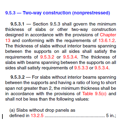
I see 2 problems here, first it means it's for flexural members, altough slabs are also flexural, i'm guessing this is for beams since in the following page there's a minimum thickness for 2 way construction.

ss_2015-11-11_at_04_14_28_xys0o8.png


The second problem is that, considering the 1st picture, for a cantilever slab with 2m of lenght and 5 years or more you'd get something like

multiplyfactor = 2 / (1+50*2) = 0,019

Which is a very small value when compared with the factor "3" that I've read around.
I apologize if my maths are wrong, I studied the EC2, not the american guides.
 
I'm not familiar with ACI but it seems that the units you are using for rho' are not the intended in the code.

Anyway, you were first worried about the long-term influence of a reduced stiffness in the transverse direction when calculating curvatures along a slab (which, although it is only one-way, takes into account the real reinforcement distribution, cracking distribution along the member, different creep factors, shrinkage strains, different frequent and sustained loads, etc). Now you settle for a multiplication factor?
 
I was worried about that when someone suggested that I could compare the behaviour of a slab with a 1m beam. In the lack of more data, a multiplication factor that stood the test of time is much more valid than the results of that comparison. Dont you think?
 
Actually, no. In my opinion, the test of time has proven multiplication factors and span/depth ratios as a mere guess.
 
I suggest a reading on page 7 of the attachment, apparently ACI and other standards have been law enforcing mere guesses earlier than 2000, or don't bother, I'm sure that every engineer using beams with a width of 1 m to determine long-term slab deflections (which surely takes 0 guesses) agrees with you.
 
 http://files.engineering.com/getfile.aspx?folder=cf28a67b-58fa-4dd1-ab19-d72d00ba1038&file=Effects_of_creep_and_shrinkage_on_the_deflection_of_RCC_two_way_flat_plates.pdf
I'll take a look on them, thank you.
I will however try to squeeze out the spread sheet to see what I can find in a more analytical way, altough I see more problems than solutions in this kind of subject. Thanks for the sheets too :)
 
I've used avscorreia sheets and a manual calculation accordingly to Paulo Cachim 's "Estruturas de Betão: Bases de Cálculo", which is also based on EC2. Altough the methods don't seem to be similar they provided at least comparable results for a 9.8m beam, but were both very far from the results of the model(more than 10cm in instantaneous deflection. In my opinion this happened because the cantilever slab has 1.5m x 9.8m, and therefore it will work primarily in one direction, making a 2-way analysis pointless. So I will determine the slab height with EC2 (which is kind of a prescritive method, but is applied to slabs, just as ACI does) and take in consideration the multiplication factor of a 1.5m * 1m beam, giving the relatively short cantilever.


But to anyone having this issue::

As of today, between EC2 and Gilbert's work, both provide a way to calculate the deflection of concrete elements taking in consideration creep, shrinkage and the cracking of a 1-way element, but be careful, on EC2 "...Simplified creep factors are used and
deflection from the curvature of the slab is approximated using a factor."

For 2-way slabs you can find some information on page 324 of Gilbert's book, chapter 8.4. However, it's a predictive method (p. 326), so it also must be taken with a grain of salt.

One other source is TR58. This technical report also deals specifically with 2-way slabs and provides several methods, altough I didn't access it, it's briefly refered in a concretecenter.com document (a example is provided in this pdf, but the support conditions are different from a cantilever).


Excuse my bad english, I hope this helps if someone comes across with the same problem.
 
cesaramorim - no need to apologise for your English, but discussions in written text often create misunderstanding, so some sketches would be helpful.

If you have a true cantilever with a span of 1.5 m and width of 9.8 m, then doing the deflection analysis as a cantilever beam of 1 m width and 1.5 m span will give almost identical results.

Or do you actually have a slab supported on three sides (one long side and two short sides), rather than a cantilever?

What do you mean when saying that predictive methods should be taken with a grain of salt? If you want to predict a deflection, how can you not use a predictive method?

Doug Jenkins
Interactive Design Services
 
It's a true cantilever with a span of 1.5m and 9.8m width, it's not supported on the 2 short sides. I believe the difference in the manual calculations and the model is because of the short span of it, which could make a 2-way analysis pointless (but i'm not entirely sure).

I said the predictive method should be taken with a grain of salt because sadly it wasn't a exact method as I hoped. So far only the TR58, which I didn't consult yet, could give exact calculations.
 
cesaramorim

There is still 2 way action. To estimate deflections for a 2way slab using one way deflection calculations, you have to break the slab down to column and middle strips, and calculate the deflection for each separately.

Then you need to look at the deflection of each strip and the overall deflection of the panel, which will be the sum of the column strip deflection in one direction and the middle strip deflection in the other direction.

If you divide your strips properly and put the correct load on each strip, you will get reasonable answers doing this as it is basically equivalent to running a grillage where the column strips are 2 grillage members in each direction on the column support lines and the middle strips are another grillage member in each direction which are supported by the column strip members in the other direction.

Then it is important to take into account the different amount of cracking, tension stiffening shrinkage and creep in each of the separate members making up the grillage of members.
 
@avscorreia

Thank you for your spreadsheet very much. I also calculated the long-term deflection of the beam according to the guidelines stated in (EC) Reinforced_concrete_design_to_eurocode_2_ed_2007 (Bill Mosley, John Bungey and Ray Hulse.) Item 6.3 page 136
I wanted to compare the results with your calculation.

Please let me know the value x center and Mfreq/Mqp?. I do not understand :(

Looking forward for your feedback.
 
@trungce

I'm glad that it is useful.

Regarding your questions:
This part of the spreadsheet generates parabolic or linear moment diagrams based on three moment values (left, center and right) for quasi-permanent combinations.
- xcenter is the position along the beam/slab referring to the point where Mqp,center is given. That is, Mqp,center can refer to any point along the span;
- Mfreq/Mqp is the ratio between the moments for frequent and quasi-permanent combinations. It is basically a scale factor used to establish the frequent combination moment diagram.

Hope it helps.
 
Status
Not open for further replies.

Part and Inventory Search

Sponsor