Continue to Site

Eng-Tips is the largest engineering community on the Internet

Intelligent Work Forums for Engineering Professionals

  • Congratulations waross on being selected by the Eng-Tips community for having the most helpful posts in the forums last week. Way to Go!

Deflection of externally FRP strengthened RC beam 1

Status
Not open for further replies.

Vimukthi

Civil/Environmental
Apr 21, 2020
23
Hi,
Does anyone know a code or a guide to calculate deflection of an externally FRP strengthened RC beam. More specifically shear strengthened by FRP u socket or wrapping. Looking around everywhere but having no luck. Anything close to this subject is OK so I can study them.
 
Replies continue below

Recommended for you

I guess my question would be, would the frp even affect the deflection of the beam?
 
Agreed, how does shear strengthening an RC beam with FRP affect serviceability deflections?
 
New design or retrofit to repair / reinforce broken RC beam??

Bit more detail needed.

Remember - More details = better answers
Also: If you get a response it's polite to respond to it.
 
Good question! I also interested this issue.
In additional, I also don't know how we can calculate the crack width extend after strengthening structural.
 
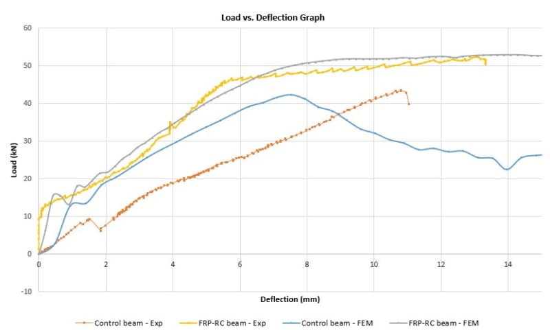
Apparently it does affect the deflection of the beam.Have a look at the attached figure. Obviously the deflection was reduced after applying FRP. And this is not even FRP sheets or laminate, its just uni-directional CFRP fabric. My guess is that it increase the Eeff of the beam where FRPs are applied. Specially look at the regions before concrete crack. I just want to know if there's any kind of guide or any attempt to address this. Doesn't matter if it is for repaired beams or new designs. There are bunch of codes that provides design guides but none of them have guides to check serviceability conditions.

Results_anzmi1.jpg
 
Good question. Let me ask you a question. How would you compute the deflection of a reinforced concrete beam if your same beam had an additional layer of reinforcing steel at the bottom? If you know how to do this then you know how to calculate the deflection of the beam with the added FRP reinforcing. Chances are that it is not going to change that significantly but might.

FRP design is based on a reinforcing system that relies on its bond to the concrete via epoxy. It has a lower elastic modulus than steel. Since it is bonded to the concrete all your stresses can be computed easily since you have strain compatibility throughout the height of the beam. Once you lose that bond your system fails which is why most designs are governed by the debonding strain. That's pretty much FRP design in a nutshell. Sure, there are a ton of other checks that need to be made and it is quite tedious but it's really not that intimidating.

Your deflection for an FRP reinforced concrete beam would be no different than your instantaneous deflection checks for a regular steel reinforced concrete beam. You need to calculate your Ieffective. Ieffective is dependent on Mcr, Ig, and Icr. The only thing that will increase due to the addition of FRP reinforcing is your Icr since the addition of FRP will increase the depth of your compression block and you will include the transformed area of FRP multiplied by the modular ratio. This increased Icr will increase your Ieffective by possibly a small amount. Since your Ieffective is also dependent on the service level moment demand, your Ieffective will actually change along the length of the beam. You will actually have portions of the beam along the length that will be uncracked. From there, you can model the beam (either by hand or with a computer program) and assign the Ieffective at each beam section to figure out the instantaneous beam deflection.

You really only need to have a good understanding of FRP design (start with ACI 440.2R) and any old Reinforced Concrete Book that discusses instantaneous deflection calculations.
 
I'm familiar with ACI 440.2R. The issue is not for flexurally strengthened RC beams by applying FRP at the soffit. It's for shear strengthened beams by u-socketing or wrapping. Somehow this affect the deflection of the beam. Maybe adhesive layer at soffit at FRP wrapped regions affect the deflection. I'll try typical method considering that adhesive layer. Also forgot to tell that FRP doesn't have any strength along the beam since it uni-directional and fiber directions are aligned with Shear stress.
 
From a theoretical standpoint, I cannot possibly see how the FRP shear strengthened concrete could have a reduced deflection due to bending forces. Possibly if your beam deflection has a large contribution to the overall deflection which is almost never the case, even in deep beams. For a column with confining FRP wrapped around the circular circumference, then yes, I can see why the deformation would be reduced due to an axially applied load. I could also understand why a circular arch member would have a reduced deflection if properly wrapped with confining FRP but only in the post-elastic state. Confined concrete will be able to reach a higher ultimate compressive strength but will not have the same effect on the elastic modulus as having a higher strength concrete would. Think Manders equation for confined concrete.

BTW, if you ever speak to a company like Fyfe, they are vehemently opposed to the idea of strengthening concrete beams using only U-wrapped FRP. Based on all of their tests, and I would seriously listen to someone like that who has a large R&D budget, they disagree with ACI 440.2R in its recommendations to increase shear strength using U-wraps. They would tell you that you need to wrap the web completely, and at the very least, anchor it at the top of the web with CFRP anchors.
 
It affect the deflection somehow. Maybe adhesive layer around the beam can affect the deflection due to bending forces I think.

Agree there need to be at least anchoring for u-socketed FRP,specially when wrapping is not possible in slab-beam systems.
 
Vimukthi said:
I'll try typical method considering that adhesive layer

How are you going to "try" this? What do you mean by that? The adhesive layer is nothing more than a thin coating of epoxy. The stuff has an extremely low elastic modulus.

I think you need to step back and examine what it is you are doing. At very best, you are about to blindly embark on some dead-end calculation endeavor based on the "guidance" of some out of context load vs deflection graph (which I am not certain you are interpreting correctly). At worst, you are about to promise some client you can reduce the deflection of his beam by adding FRP shear strips which would be completely erroneous.
 
This is not for some client. It's an old experimental research of mine. I meant the plotted results. I'm just trying to understand it in a more theoretical level. Or maybe launch a new research since nowhere this is explained. The biggest difference were shown in slopes of regions before cracking occur. After cracking slopes are pretty much the same. Since I have all the time I need due to lockdown I'm gonna try to figure it out from scratch.
 
Its a 200 X 200 section with 2T12 r/f at top and bottom each. CFRP layer thickness is 0.168 mm and epoxy adhesive layer can be assumed as 1mm. CFRP fabric is embedded in the epoxy layer. For this case CFRP is applied (wrapped) 450mm at each end.
 
Span?
Supports?
Load arrangement?

Unless the beam is failing in shear, I don't see how wrapping the end 450 mm would have the effect shown in your graph.

Doug Jenkins
Interactive Design Services
 
It was designed to fail in shear with low shear r/f. It has 2 m span and simply supported. Control beams failed in shear and after applyingg CFRP, failure mode became flexural. Four point bending arrangement was used for testing.
 
Maybe you'll enjoy the liked paper that directly related to your interest. Link
 
The reduction in deflection results from shear flow developed at the bond interface between the FRP and the concrete.

 
Agree with Ron. The strengthening FRP obviously is provided near the end supports of the beam. While it helps resisting the excessive shear directly, the bond produces an effect that restricts/minimizes beam rotation as well. As a result, the deflection is reduced.
 
Status
Not open for further replies.

Part and Inventory Search

Sponsor