Continue to Site

Eng-Tips is the largest engineering community on the Internet

Intelligent Work Forums for Engineering Professionals

  • Congratulations SDETERS on being selected by the Eng-Tips community for having the most helpful posts in the forums last week. Way to Go!

Deflection of Stacked Beams with Different Beam Sections 7

Status
Not open for further replies.

Logan82

Structural
May 5, 2021
212
Hi,

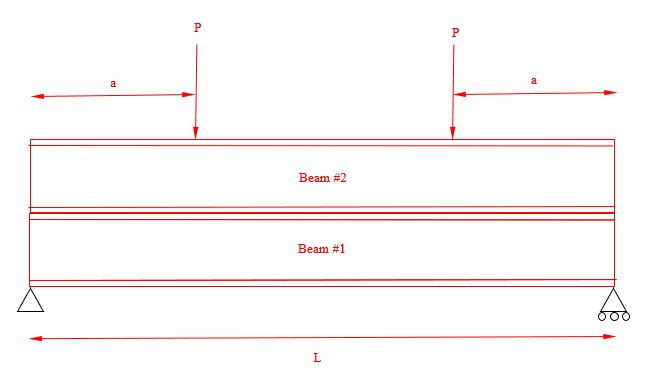
What would be the equation of the deflection of the two beams stacked stacked on each other? I am looking for the deflection at a distance "a" from the support.
2022-09-29-14.09.03_qipcor.png


Assumptions:
- The two beams are not linked to another, they are just stacked.
- We can assume that there is no friction.
- The two loads are symmetrical.
- The two beam shapes are different.

I know that:
- The deflections are equal (Δ1 = Δ2).
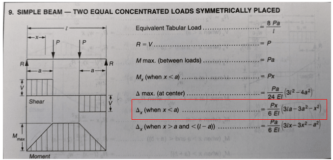
- The equation of the deflection if there was one beam would be:
Δx = (P*x*(3*L*a-3*a^2-x^2))/(6*E*I)
Since we are looking for the deflection at x = a, then:
Δa = (P*a*(3*L*a-4*a^2))/(6*E*I)
2022-09-29-14.13.30_ch8akv.png
 
Replies continue below

Recommended for you

Wouldn't the load on Beam #1 actually be a set of (2) distributed loads based on the 9*k width distribution (or whatever the recommendation is for bearing distribution on a web...sim to stiffener loads?

Assuming Beam #1 is stiffer than Beam #2, I would probably just add the I and call it a day. Probably want to include more self-weight on Beam #1 as well.
 
summing the Is is an engineering reality answer, but (probably) not the Truth.

there are many, many threads on this question.

beam 2 is balanced by a distributed reaction (onto beam 1).
beam 1 is a simply supported beam with a distributed load.
the external reactions are easy to calc (= P) but the deflected shape is not simple (if you want the Truth).

"Hoffen wir mal, dass alles gut geht !"
General Paulus, Nov 1942, outside Stalingrad after the launch of Operation Uranus.
 
skeletron - yes, they would. But I think the influence on the deflected shape of beam 1 would be trivial.

rb1957 - you are correct, the reality is a bit more complicated than summing them. But so is everything we do as structural engineers working in building design. So perhaps we should pose this question to the OP: why? Is this an academic pursuit? Sorta feels like a PE review question. Or is this a design question? If academic, then break out the FEM and lets dig into it. If it's a PE review question or a design question....go for the simple summation.
 
I certainly agree with phamENG regarding the combined, non-composite I value being the way forward in a production engineering setting. And it should be somewhat conservative so long as both beams make it out to the support. Things get a bit weird when the upper beam is partial length. We had some fun with that condition back in 2015: Link. Theory, models, DIY testing...
 
Seems like a purely academic exercise if the top beam isn't connected to anything, and we're in the "no friction" world.
 
I was just about to post a link to the 2015 discussion, but I see KootK already posted it.

A different case there, but it's worth reading anyway.

For this case I think the top beam would contact the lower beam at the ends and at mid-span, and the deflection would be greater than for a single beam with the combined non-composite I value, but I might be wrong.

Doug Jenkins
Interactive Design Services
 
For this case I think the top beam would contact the lower beam at the ends and at mid-span, and the deflection would be greater than for a single beam with the combined non-composite I value

Forget that. The load is transferred to the beams in proportion to their flexural stiffness, so the total deflection is the same as a single beam with the sum of the two beams stiffness values.

For a real beam with non-zero friction the deflection would of course be less than that.

Doug Jenkins
Interactive Design Services
 
Thank you all for your answers! It is really appreciated.

phamENG said:
rb1957 - you are correct, the reality is a bit more complicated than summing them. But so is everything we do as structural engineers working in building design. So perhaps we should pose this question to the OP: why? Is this an academic pursuit? Sorta feels like a PE review question. Or is this a design question? If academic, then break out the FEM and lets dig into it. If it's a PE review question or a design question....go for the simple summation.
This is for a structural evaluation of a real structure.
 
This is for a structural evaluation of a real structure.

I think PhamENG gave the conservative upper bound for the deflection in his first response - it would be calculated using the sum of the moments of inertia, ignoring friction between the beams.

I also agree with IDS that the actual deflection will be a value something less than that, due to some composite action resulting from friction between the beams. Analyzing the system with a limited amount of shear capacity at the interface of the two beams is, as far as I know, a fairly complicated analysis. Maybe there's a direct solution, but I would only know how to do an iterative solution. It would be a solution with a huge error factor, due to the variability in the coefficient of friction and the difficultly in estimating the normal force on the interface.

Rod Smith, P.E., The artist formerly known as HotRod10
 
Questions that I ponder -

1. How does one know that the deflections are equal?
2. Do the free ends of the upper beam lose contact with the lower beam, and is this accounted for in the equal deflection statement?
 
1. How does one know that the deflections are equal?
2. Do the free ends of the upper beam lose contact with the lower beam, and is this accounted for in the equal deflection statement?

If the loading (load applied to the top beam) and support conditions (pinned supports at the ends of the beam) are similar to the OP's diagram, basic structural mechanics dictates that the beams will stay in contact along the entire length. So as long as the beams were in contact before the load was applied, the beams will deflect equally.

Rod Smith, P.E., The artist formerly known as HotRod10
 
One issue not being considered is the stiffness (rotational and translational fixity) of the beam end connections. It will be impossible for the beams to stay in contact and deflect together assuming both ends of both beams are connected to something (which they must be since the OP stated the beams were not connected to each other)
 
MotorCity - The OP says the beams are not linked but are stacked, and the diagram shows the lower beam is pinned at one end and has a roller at the other.

The only difference in the deflections would be the compression in the web between centre lines, which would be negligible in the context of the question, but we can get rid of that if we use the deflection of the top surface of the lower beam and the bottom surface of the upper beam.

Doug Jenkins
Interactive Design Services
 
I do not understand why the ends of the upper beam cannot/will not lift off the lower beam. Plate corners lift under vaguely similar conditions. The lower beam seems like an elastic foundation with contrained ends. I would be happy to learn something out of this.
 
The top beam must deflect to transfer load to the lower beam, so there must be some load transferred through the top beam to the support, so the top beam must be in contact with the lower beam at the ends.


Doug Jenkins
Interactive Design Services
 
Plate corners lift under vaguely similar conditions. The lower beam seems like an elastic foundation with contrained ends.

If the beams had radically different stiffnesses, it could be possible to see the top beam deflecting differently than the bottom one, but if the diagram is anywhere close to being to scale, I don't see that happening.

Rod Smith, P.E., The artist formerly known as HotRod10
 
For Bernoulli beams with zero depth, regardless of their relative stiffness, the loads will be transferred between the beams at the point of application of the forces in proportion to their stiffness, so that the shear force, and bending moment are in proportion to the beam stiffness over the full length. The curvatures and deflections will therefore also be equal over the full length, and the beams will be in contact over the full length.

For real beams with depth and shear deflection it gets more complicated, but the deflections will be close to those found with the simplified assumptions.

Doug Jenkins
Interactive Design Services
 
Status
Not open for further replies.

Part and Inventory Search

Sponsor