Continue to Site

Eng-Tips is the largest engineering community on the Internet

Intelligent Work Forums for Engineering Professionals

  • Congratulations IDS on being selected by the Eng-Tips community for having the most helpful posts in the forums last week. Way to Go!

Deflection of Stacked Beams with Different Beam Sections 7

Status
Not open for further replies.

Logan82

Structural
May 5, 2021
212
Hi,

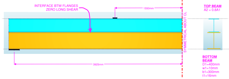
What would be the equation of the deflection of the two beams stacked stacked on each other? I am looking for the deflection at a distance "a" from the support.
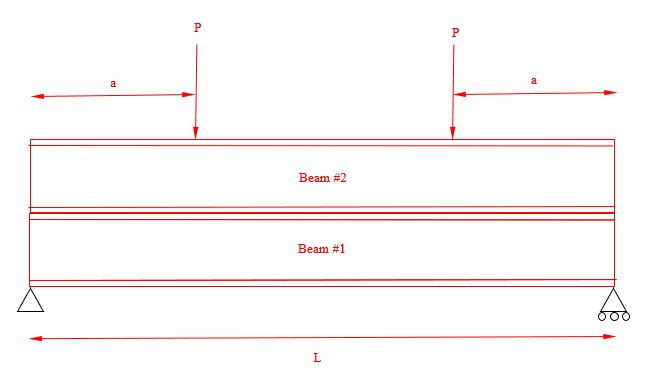
2022-09-29-14.09.03_qipcor.png


Assumptions:
- The two beams are not linked to another, they are just stacked.
- We can assume that there is no friction.
- The two loads are symmetrical.
- The two beam shapes are different.

I know that:
- The deflections are equal (Δ1 = Δ2).
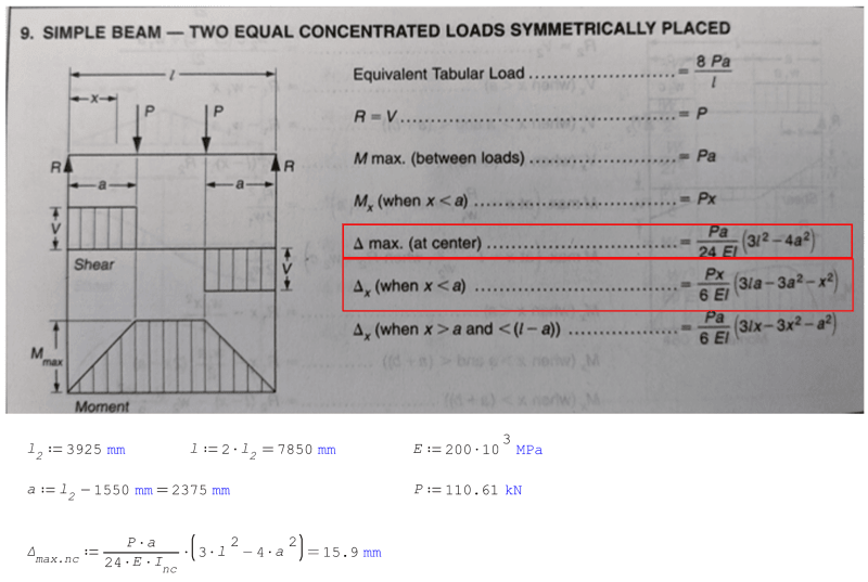
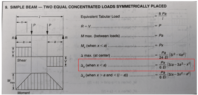
- The equation of the deflection if there was one beam would be:
Δx = (P*x*(3*L*a-3*a^2-x^2))/(6*E*I)
Since we are looking for the deflection at x = a, then:
Δa = (P*a*(3*L*a-4*a^2))/(6*E*I)
2022-09-29-14.13.30_ch8akv.png
 
Replies continue below

Recommended for you

IDS - I understand the top beam and bottom beams are not linked, but the top beam is not connected to anything. That makes no sense. The top beam is not stable. Is it really just sitting there? I hope not. My point is that we are ignoring the connections of the top beam - which I hope do exist for the safety of anyone that gets near this thing.
 
yes, "clearly" this is a text question, not a real world problem.

if the two beams were bolted together it'd be easier to see that the two would behave as a single composite section (not summed I's). "summed I's" could be the solution for two beams with a slip surface between them. I agree "summed I's" is a conservative practical solution, but I doubt it is the "Truth".

"Hoffen wir mal, dass alles gut geht !"
General Paulus, Nov 1942, outside Stalingrad after the launch of Operation Uranus.
 
phamENG said:
No problem, Logarn82.
I'm sorry that I mispelled your name in the quote in my previous post haha, I have done the correction. Thank you for your help, you gave me many good advices over the last years.
 
MotorCity said:
IDS - I understand the top beam and bottom beams are not linked, but the top beam is not connected to anything. That makes no sense. The top beam is not stable. Is it really just sitting there? I hope not. My point is that we are ignoring the connections of the top beam - which I hope do exist for the safety of anyone that gets near this thing.

There are some bolts that connect the top and the bottom beam, but there are not enough bolts to make sure that the top and bottom beam act as one beam.
 
Logan82 said:
I'm sorry that I mispelled your name in the quote in my previous post

No worries. It's amazing how many people add the 'r' in there.

Logan82 said:
There are some bolts that connect the top and the bottom beam, but there are not enough bolts to make sure that the top and bottom beam act as one beam.

Be careful here. Having any bolts means that they'll try to act as one, but may overload and fail the bolts on their way to actually behaving like you're assuming. You could provide slotted holes or just make sure that, when loaded, the differential movement between the flanges is tolerable at the bolt locations.
 
I have followed up on this thread with a another thread:

It is the same situation, but this time I am asking the following questions:
- What would be the maximum strain at the tension fibre of one of those two stacked beams?
- More specifically, what should I take for the distance between the neutral axis and the fiber in tension "y"?
 
phamENG said:
Be careful here. Having any bolts means that they'll try to act as one, but may overload and fail the bolts on their way to actually behaving like you're assuming. You could provide slotted holes or just make sure that, when loaded, the differential movement between the flanges is tolerable at the bolt locations.

Good point.
 
There will not be enough longitudinal slip to fail the bolts. The same as it being difficult to bolt beams together to achieve true composite action. By the time bolts have engaged it’s sagged a fair way.
 
Tom, in most cases, absolutely. It was more of a philosophical statement. We tend to simplify things a lot in our profession, which is good and necessary. But we need to be aware of the consequences of our simplifying assumptions.

And we don't know what failure will be for this. When they torque the bolts down, the friction will engage some composite action. When that is overcome, it will slip and deflect more. If that happens at 100% dead and 5% of service live load, will that be a serviceability failure?
 
No, because No composite action was assumed.
 
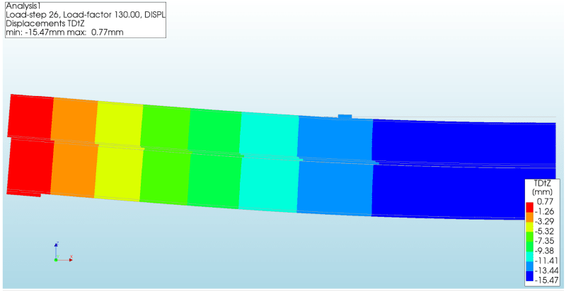
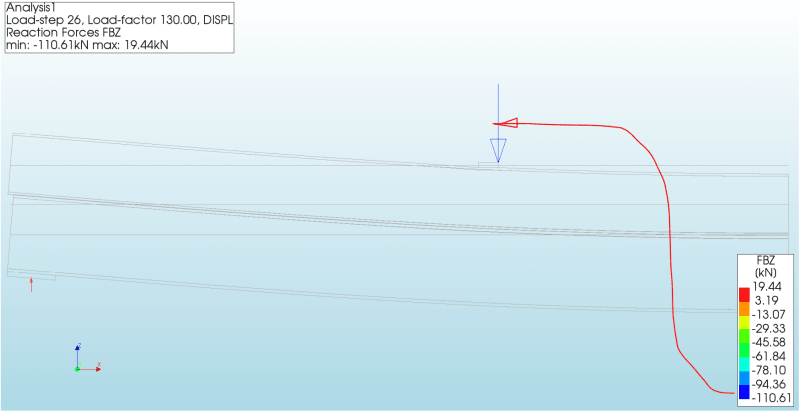
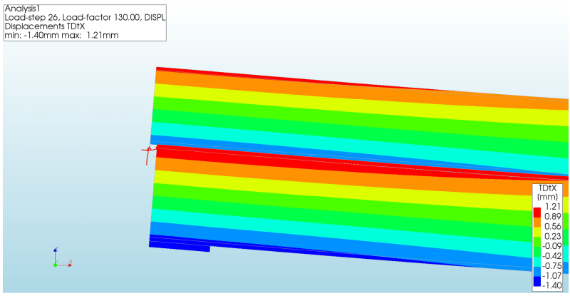
Picture time. Needed a break from real work, so I created a model of this. This has a fictitious interface between the flanges that permits zero longitudinal shear. This model does not include any load distortion effects.

img1_zhrbzk.png

img2_hrtkya.png

img3_gd5m7w.png

img4_q5qyhq.png


I found the sum of I1+I2 compares well to the model. It will not be exact due to the width of the loaded shape.
img5_d5sxuy.png


I think Pham's note about the assumption can be seen well in the image below. For the assumption of zero longitudinal shear to be true, you would need around 3mm of lateral displacement between the two profiles at the end in this example.
img6_pnjtqg.png
 
Brad805 - curious how you got the FEA to run with the unconstrained upper beam.
 
I'm surprised this isn't completed, yet. Calculate the deflection based on I1+I2 as noted above. Then proportion the load based on the relative deflections. In this manner the deflection of the two beams are the same with the appropriate portion of the total load. This assumes there is no friction interference at the interface... greased beams? [ponder]

So strange to see the singularity approaching while the entire planet is rapidly turning into a hellscape. -John Coates

-Dik
 
dvd, this software has interfaces. I used an interface between the two beams where the XX is released. Both the YY and ZZ values are perfectly restrained. Not physically possible, I know. At the middle of the beam I have an XX restraint to both beams since it was assumed the beam assembly is symmetrical.

dik, I was curious if I could replicate this in a model.
 
If your software can provide for same deflection values, you should. It's so simple that I'd just punch it out on my calculator, or if I had a bunch of them, do a quick SMath program. I almost never use FEM... mostly, it's not needed and the precision is not normally warranted. About 40 years back I was involved in a court case (as an expert) and the prof that I was challenging used FEM. It was at the time that shear friction was coming into its own, but wasn't recognised in Canada. The prof had done an FEM model of a dowelled joint and had determined the max bearing on the concrete was 13ksi... I simply asked him what would be the effect if the concrete yielded and redistribute the loads. He couldn't answer. It was a shame because he was one of my referees for getting prof registration. This also prompted me to write my first 3D FEM program that I used for designing gas bearings using piezoelectric ceramics to change from a physical bearing to a gas bearing at high revs... [pipe]

So strange to see the singularity approaching while the entire planet is rapidly turning into a hellscape. -John Coates

-Dik
 
It would be easy enough in this case to add bolts, or assign an interface values between the two planes to estimate the real structure behavior. That SMath routine would be a tad more complicated.
 
Nice work Brad805! Thank you all for your answers.

If I were to design a beam built of two steel sections, I would have used friction connections to make sure there is no slippage. In this case, I am evaluating an existing structure. I am puzzled for the following reasons:
[ul]
[li]I see no specification in the drawing (from the 1970s) that they are slip critical.[/li]
[li]If I consider that the two beams are stacked, it remains that in reality some bolts will try to resist the shear. But even if all bolts worked together with no slip, there are not enough bolts to resist the shear flow. [/li]
[li]If I add some bolts so that I can consider that the two beams are composite, some bolts could still slip since the existing bolts are not friction connections. [/li]
[/ul]
Is there an option other than replacing the bolts for slip critical connections and putting sufficient bolts to resist the shear flow?
 
Weld the flanges together with intermittent fillet welds is another option. There are also some clamps but IDK if I would rely on those permanently for this application.
 
As you increase the loading, the deflection will increase based on the beams resisting independently (I1 + I2) until the slack between the bolts and the holes is taken up. Additional loading will be resisted by the composite section, until the bolts shear off, then it's back to the deflection based on I1 + I2. If the deflection becomes unacceptable at any point, or if the bolts shearing off comes at an unacceptably low loading condition, you have to add more bolts, or replace the bolts with ones that have greater shear capacity (assuming the bearing capacity on the holes is adequate).

Rod Smith, P.E., The artist formerly known as HotRod10
 
But would you say that slip critical bolts are mandatory for composite beams? Are bolts in bearing allowed?
 
Status
Not open for further replies.

Part and Inventory Search

Sponsor