Sam165
Structural
- Sep 28, 2020
- 12
Working on a rehab project of a four story multi-family apartment building. The front balcony beam (running parallel to railing) was water damaged to the point of needing to be replaced. Contractor replaced the beam per my recommendation and I was out there doing a QA this morning. While doing my QA I noticed the perpendicular glulam beam that face hangers onto the replacement beam is delaminating at the bottom plies and has a diagonal crack propagating from the over-fastened replacement hanger. The beam is a 3.5”x9.5” Anthony Power Beam that spans 7’-0”. It is supporting perpendicular top chord bearing floor trusses that span 9’ on either end. Live load is 100psf and dead load is 40psf.
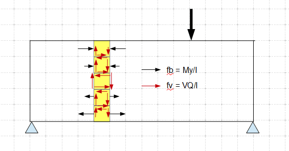
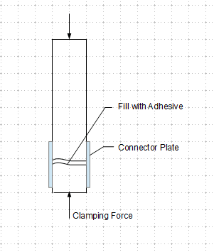
I’m thinking of specifying lag screws that are driven from the bottom of the beam to fasten the plies back together. I’m not too worried about the diagonal crack. To figure out the required spacing of the screws, I calculated the max horizontal shear by determining the max bending stress and resolved that into a force couple. I feel like I need to take only a portion of the bending stress that is being resisted by the bottom plies (delaminating plies) but I wanted to get some input from you on how best to proceed. Thanks in advance!
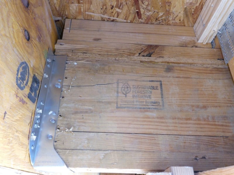
Left face of beam looking into floor cavity.
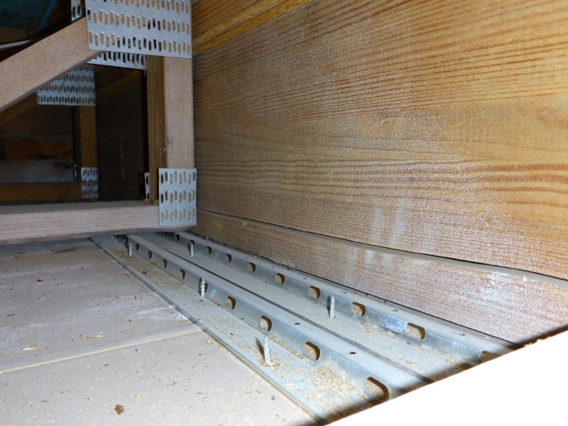
Left face of beam:
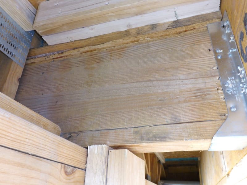
Right face of beam:
I’m thinking of specifying lag screws that are driven from the bottom of the beam to fasten the plies back together. I’m not too worried about the diagonal crack. To figure out the required spacing of the screws, I calculated the max horizontal shear by determining the max bending stress and resolved that into a force couple. I feel like I need to take only a portion of the bending stress that is being resisted by the bottom plies (delaminating plies) but I wanted to get some input from you on how best to proceed. Thanks in advance!
Left face of beam looking into floor cavity.
Left face of beam:
Right face of beam: