bluestar9k
Structural
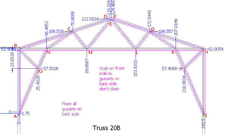
Shown below is an image of the truss that spans 4 walls. The 2 interior supports were evaluated 2 different ways. Initially the interior supports were set as pinned connections and after running an evaluation of the truss the results indicated that these supports produced horizontal forces of 1000 lbs each which pointed toward the center of the truss. The second method considered the 2 interior supports as roller supports which produced deflections of 1/8” toward the center of the truss.
The cap plate is 2” x 4” Grade 2 S. Pine, the trusses are set 24” OC and the longest laterally unsupported wall is 14’. A deflection of 1/8 in the cap plate seems unacceptable and subject to creating cracks in the ceiling. The 1000 lb. lateral load set 24” OC greatly exceeds the capacity of the cap plate.
Initial thoughts for reinforcement:
1. Sandwich a steel plate (thickness yet to be determined) between the upper and lower cap plates.
2. Replace the 2x4 cap plate with a 4” WF, double channel or double angle iron.
Would appreciate any thoughts you might have.


