Continue to Site

Eng-Tips is the largest engineering community on the Internet

Intelligent Work Forums for Engineering Professionals

  • Congratulations KootK on being selected by the Eng-Tips community for having the most helpful posts in the forums last week. Way to Go!

DESIGN: Need to Reinforce Interior Wall Cap-Plate for Lateral Load

Status
Not open for further replies.

bluestar9k

Structural
Nov 11, 2016
31
Shown below is an image of the truss that spans 4 walls. The 2 interior supports were evaluated 2 different ways. Initially the interior supports were set as pinned connections and after running an evaluation of the truss the results indicated that these supports produced horizontal forces of 1000 lbs each which pointed toward the center of the truss. The second method considered the 2 interior supports as roller supports which produced deflections of 1/8” toward the center of the truss.

The cap plate is 2” x 4” Grade 2 S. Pine, the trusses are set 24” OC and the longest laterally unsupported wall is 14’. A deflection of 1/8 in the cap plate seems unacceptable and subject to creating cracks in the ceiling. The 1000 lb. lateral load set 24” OC greatly exceeds the capacity of the cap plate.

Initial thoughts for reinforcement:
1. Sandwich a steel plate (thickness yet to be determined) between the upper and lower cap plates.
2. Replace the 2x4 cap plate with a 4” WF, double channel or double angle iron.

Would appreciate any thoughts you might have.
Truss_zhpwmp.png
 
Replies continue below

Recommended for you

How much of the 1/8" movement is due to dead load?

Most of that would occur prior to installing plaster or gypsum board sheathing.
So if the live load deflection is only 1/16" or so that may not be significant enough to worry about.

Check out Eng-Tips Forum's Policies here:
faq731-376
 
In addition - I'm not sure a stud wall could even begin to generate enough stiffness to resist 500 lbs/ft, so your roller support is probably closer to reality.

Check out Eng-Tips Forum's Policies here:
faq731-376
 
Agree with JAE, but as to the top plate, surely that would be a double plate.

Transporting and handling a truss of that shape will be a nightmare. I suggest that it will actually be 3 trusses.
 
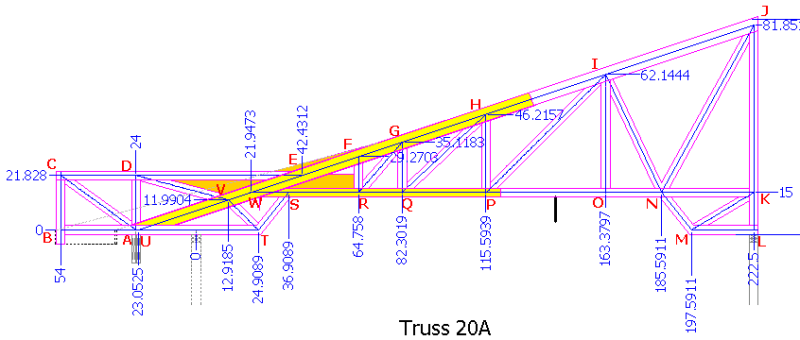
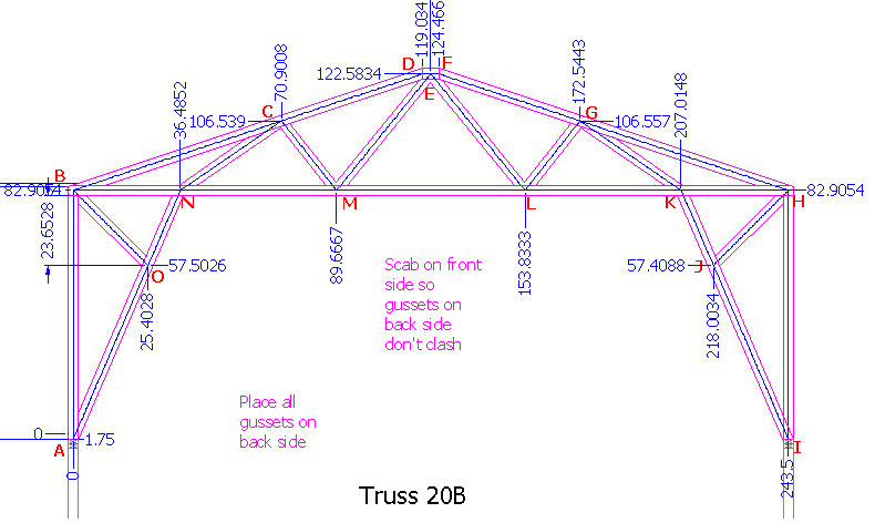
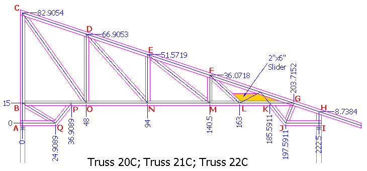
Quite correct, hokie66, quite correct. The cap plate is a double 2x4 and the initial truss image was a composite of 3 trusses as shown below.

Truss20A_yryyci.png
Truss20B_kpkaz9.png
Truss20C_qptsbh.png


Also quite correct JAE, the deflections from dead load appear to only be around 1/3 of total LRFD load deflection. See table. The deflections were assumed to be linear/load.
Deflections_crllih.png


So in a worst case scenario it appears there would be a .0838 deflection (or around one and a half 16th of an inch) that hopefully would close when the live load dissipated.
 
Not sure how you are calculating your deflections but typically they are analyzed at a service load condition (ASD), not at strength loads (LRFD). Also the horizontal deflection would theoretically distribute both ways, so each side would push out at half your calculated displacement, which is pretty much nothing. From what I'm seeing the deflection magnitudes are small enough that I don't think it's an issue. I don't know if your analysis is taking deformation of the truss chords into effect but probably the only thing that's getting you that horizontal deflection is those diagonal supports at each end of the middle truss that are likely limiting vertical deflection of the middle truss and translating it into horizontal deflection.
 
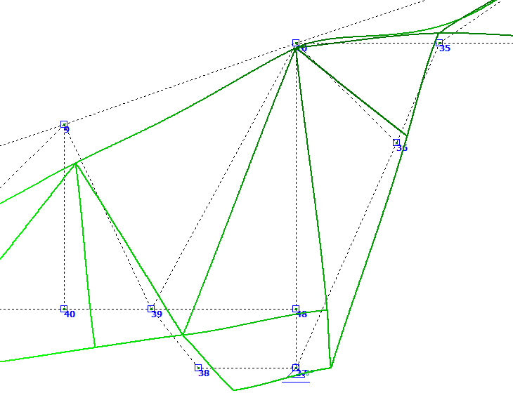
Oh, I quite agree dnlv, (ASD) is most commonly used in serviceability limit analysis for deflection, vibration, clearances, etc. However, I selected strength based limits (LRFD) for the truss design and of course ASD and LRFD methods should not be mixed. Anyway, the frame analysis application also provided displacements which I chose to consider because it was expected to produce the worst case displacements. Shown below is a close-up of the composite truss displacement at the interior wall.

Displacement_kvh61p.png


When each truss was analyzed separately the right side of 20A truss displaced to the right and the left side of 20B displaced to the left. However, when analyzed collectively the net displacement was to the right. Now, the vertical displacement of truss 20A over its full horizontal length is ¼”; however, this is spread over 20’ and is not expected to create cracking in the sheetrock. On the other hand the horizontal displacement at the interior wall may cause a discontinuity displacement adequate to create cracks and that was the concern.

Perhaps anchoring the trusses to the cap-plate of the interior wall will force the interior wall to move with the truss deflection (1/8” over 14’) thus eliminating the potential discontinuity and subsequent cracking. The calculated 1000 lb horizontal force for a pinned support at the wall would dissipate (be absorbed by the truss) as the cap plate deflected. However, this concept would only be applicable to a portion of the center section of the 14’ wall; and, as consideration of the trusses moved closer to the laterally supported ends of the wall the calculated 1000 lb horizontal force on the cap plate would become a concern and subject to reinforcement.
 
Status
Not open for further replies.

Part and Inventory Search

Sponsor