Hello,
I am a mechanical engineer working now as a project engineer to handle design and commissioning of heated bitumen lines as I work in the bitumen industry.
My most recent project is design of a buried bitumen line extending only for 100 m ( my research online shows that this distance is very small as compared to already established pipelines in the world) which has to be in an encasing pipe( stainless steel due to facility requirement, helps as the earth loading and soil and pipe interaction will be limited to encasing line rather than my process line) and needs to have concrete pit at the start and end point. Operating temperature and pressures are 150 C and 6 bar for the 250NB SCH40 A106 B line.
I am learning the field as I am going and to be able to do this job I have been using Plant 3D , Inventor and CAEPipe analysis but I am no expert in all of these software and I am just trying to achieve the best design possible before submitting it for verification.
Due to an expansion of 200 mm on the heated line, my first thought was to use axially compression bellows ( hinged joint analysis and gimbal joints seemed very complex to me ) but I was suggested to rely more on pipe flexibility and refrain from use of bellows if that does the job. The expansion loop size estimated from Pipedata pro was 6X6 and I am not having that space to be able to accommodate a loop. So I went for an expansion joint setup and taking considerations from expansion joint design from Peng Peng designed my model in CAEPipe and put in a bellow for catering the expansion.
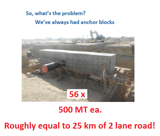
I thought that using an anchor block in one of the pits which, will be closer to the expansion joint (based on recommended spacing),to absorb the forces I am getting from the pipe stress analysis software would be a viable solution. Is there any good advice for tackling the project above in a better and more efficient way?
My reason for posting a description like the above is that I am seeking advice from professionals as to what all I am doing wrong here as I have very less experience and guidance at the moment on this project.
Thank you for your input.
The file link generated is:
I have added some new photos for the alternate approach of flexible expansion loops from stress analysis software as follows:
https://files.engineering.com/getfile.aspx?folder=98ffbb04-1611-49e4-9110-5861a3ec3085&file=1111.JPG
https://files.engineering.com/getfile.aspx?folder=dc81cd99-6e18-43f5-875a-8861220d0252&file=1112.JPG

