Eng-Tips is the largest engineering community on the Internet

Intelligent Work Forums for Engineering Professionals

  • Congratulations waross on being selected by the Tek-Tips community for having the most helpful posts in the forums last week. Way to Go!

Design of a buried heated bitumen line in an encasing pipe 4

Status
Not open for further replies.

Shiv1295

Mechanical
Apr 13, 2020
10
0
0
NZ
Hello,

I am a mechanical engineer working now as a project engineer to handle design and commissioning of heated bitumen lines as I work in the bitumen industry.
My most recent project is design of a buried bitumen line extending only for 100 m ( my research online shows that this distance is very small as compared to already established pipelines in the world) which has to be in an encasing pipe( stainless steel due to facility requirement, helps as the earth loading and soil and pipe interaction will be limited to encasing line rather than my process line) and needs to have concrete pit at the start and end point. Operating temperature and pressures are 150 C and 6 bar for the 250NB SCH40 A106 B line.
I am learning the field as I am going and to be able to do this job I have been using Plant 3D , Inventor and CAEPipe analysis but I am no expert in all of these software and I am just trying to achieve the best design possible before submitting it for verification.
Due to an expansion of 200 mm on the heated line, my first thought was to use axially compression bellows ( hinged joint analysis and gimbal joints seemed very complex to me ) but I was suggested to rely more on pipe flexibility and refrain from use of bellows if that does the job. The expansion loop size estimated from Pipedata pro was 6X6 and I am not having that space to be able to accommodate a loop. So I went for an expansion joint setup and taking considerations from expansion joint design from Peng Peng designed my model in CAEPipe and put in a bellow for catering the expansion.
I thought that using an anchor block in one of the pits which, will be closer to the expansion joint (based on recommended spacing),to absorb the forces I am getting from the pipe stress analysis software would be a viable solution. Is there any good advice for tackling the project above in a better and more efficient way?
My reason for posting a description like the above is that I am seeking advice from professionals as to what all I am doing wrong here as I have very less experience and guidance at the moment on this project.
Thank you for your input.
The file link generated is:

I have added some new photos for the alternate approach of flexible expansion loops from stress analysis software as follows:


Replies continue below

Recommended for you

OK,

Your sketch seems to show your inner bitumen pipe is in essence inside a tunnel (albeit a small one) with free movement of the inner pipe and presumably its insulation and ?steam tracing?

If 200mm is your total expansion for the inner pipe, then 100mm would seem to be able to handled by a standard pipe loop at both ends, but you may need to acnhor the pipe in the middle of the tunnel to ensure equal movement.

Bellows sound good, but are costly and depending on the number of times you start and stop this line can fail over repeated actions. Alos I beleive they are much better at flexing than straight axial movement as the forces are often quite high to get them to move.

Other things people do is to initially heat the line before final fixing to pre expand it, but bitumen is quite warm for this so may not be practical.

In general it is usually better to allow movement to be accommodated rather than trying to lock in forces with large blocks as the forces quickly become very significant ( hundreds of tonnes force)

Remember - More details = better answers
Also: If you get a response it's polite to respond to it.
 
Shiv,

Contact one of the experienced "double pipe" vendors and ask about the normal and customary materials choice for your situation.

PERMA-PIPE is one of the oldest and best, IMHO ... but there are others ..


They will suggest a configuration for you and discuss system thermal expansion with you.

Your need for an expensive expansion bellows may not be necessary

Suggest that you rely heavily on those that have done this before ...


Please respect us ..... Complete this thread and tell us about your final design and choices ...


MJCronin
Sr. Process Engineer
 
Shiv1295 (Mechanical);

The piping sketch attached is already an expansion loop and seems you will not need any other expansion bellow/loop.
In order to reduce the 200 mm one way expansion , the piping may be heated to average tem. (150 c+ Ambient temp)/2 during installation.

I just want to remind two points;

i) What about insulation?

ii)The piping sketch apparently low-point pocket and shall be avoided for the bitumen piping. (during shot down period the hot bitumen will harden ).
 
Thank you so much everyone for your replies, this was my first thread didn't expect replies for days. This indeed is a great site.
 
Hello LittleInch,

Yes, the process line is inside the tunnel supported on spider supports and hence centralised. It has a rockwool insulation and heat tracing. My client wants to use thermal oil heating and the pipe has to be inside the process line. Bit tricky for me.

Yes, I did notice advice on bellow long lasting problems. The problem that I have here,( sorry for not being more descriptive) is that we are gonna fix in the tunnel first through horizontal directional drilling and then install the process line inside the tunnel. That's the scope of work I ahve been given and hence the central anchor point seems to be difficult to achieve. would have been great if I could do trenched installation but I dont and will not have a provision for it. That's why I resorted to axial compression bellow placed close to one of the pits so that with regular inspection if it requires replacement, it can be done. There might be as much as 10 cycles per year of this line as it is just a load-to(once) and load-from(nine times maybe) line.
Can there be a way to let go of the below with this trenchless installation problem?
I will try some iteration for the loops today instead of completely ignoring a trial.

The axial force provided by the pipe stress analysis software on the pit anchor point is 60.8kN. Can this be treated as a realistic force or in the field the situation can be a lot different?

Thank you again for your input.
 
Hello HTURKAK,

Yes, I will try one iteration without the bellows and see how bad it goes. I was so much focused on the thermal expansion catering and my space limitations that I didn't think of a novel solution with just pipe routing.
I will play around today and come up with a loop system.
The insulation is rockwool insulation.
"The piping sketch apparently low-point pocket and shall be avoided for the bitumen piping. (during shot down period the hot bitumen will harden )." Pardon me but I didn't understand the low point pocket.
Thank you for your input.
 
Hello MJCronin,

Thank you for the link. My first search was double containment systems and I did go to PERMA-PIPE. I looked at the same pdf and due to the legal requirements I cannot use a PVC encasing pipe anymore, that was the initial idea to use PVC PN16 or something but it doesn't qualify as a containment system for hot bitumen.
That's a good advice to ask them for some other material combination and whether they can do it for me but then there is another hurdle there, I am in NZ and they don't have an office here. I don't know if they will be interested in investing time on this. I might be wrong. Please advise. Thank you for your input.
 
I had to edit my original post, based on an expansion differing from your's. I got half of your 8", but anchor force is still very high.

I don't see any critical equipment attached to this pipe segment, so why are you worried about stopping the expansion here? Without anchors on either end, you can assume that the pipe will expand an equal amount in each direction, making that 100 mm at each riser. I feel that you must accomodate the expansion by letting the above ground pipe move those 100 mm in each direction at the top of the riser and transferring the expansion through the horizontal pipe elsewhere, somewhere that you can place a proper expansion loop or some other kinds of long 90 bends. THERE IS NOOOO point trying to anchor it at both ends right there, that will be a huge force, somewhere around 400,000 lbs at each (proposed) anchor. If you can't do any of that, try lowering the underground, or raising the above ground pipe some more increasing the depth/height of the big expansion loop that you already have there. But you will need much, much more vertical offset; maybe 4 or 5 meters. Any less will overstress the pipe with bending moment stress.

200mm/25.4 = 8 in expn?
but,
150C * 9/5 = 270F 270+32=302F
(302-70 installation temperature)F x 0.000006 in/in-F = .0014 in/in
100m pipe length x 3.28 = 328 ft x 12 = 4000 in
4000 x .0014 = 5.6 in expn

Anchor force = 5.6" x 12in^2 pipe steel area * 30,000,000 psi / (328 ft x 12"/ft) = 512,000 lbs (2250+/- kN)

“What I told you was true ... from a certain point of view.” - Obi-Wan Kenobi, "Return of the Jedi"
 
Please have a look at the additional files posted from the expansion loop method in the pipe stress analysis software in the original post.

 
Electric heat tracing is better from a reliability perspective. At 150degC and 100m length in this buried application, you would be looking at HTEK style heat tracing from Thermon for example.
 

Shiv1295 (Mechanical) said:
"The piping sketch apparently low-point pocket and shall be avoided for the bitumen piping. (during shot down period the hot bitumen will harden )." Pardon me but I didn't understand the low point pocket.

The sketch shows that the underground portion is immersed U-TUBE in the ground (low-point pocket) and one can not drain the depressed portion with gravity. Low-point pockets should be avoided for the ; Steam ,Slurry, bitumen, wax,Pump suctions...) lines.

According to your explanation , the line is not heated and insulated with rock wool. If the low point pocket is inevitable, at least that portion shall be heated (with steam jacketing , heat trace ..) to avoid the cooling and solidifying the bitumen.

Regarding the partial heating of the piping, I proposed to heat the underground horizontal portion to reduce the over stressing of risers at both sides. If the ambient temp. 30 degr. the operation temp . 150 degr. the average is 60 degr. If the horizontal portion is heated to 60 degr during erection, the total expansion will be 75 mm during operation.
P.S. I have calculated the total expansion 150 mm . for 150 degr.operation, 30 degr. ambient temp.

Good Luck.
 
No dimensions are shown on those. Otherwise they change nothing. Where's the numbers?

So if the pipe stress run shows no overstress (a bit hard to believe at elbow 210), why think of using a compression bellows? Those need to be avoided whenever possible. Basically they are to be used at critical, pumps, compressors, sensitive nozzles, and near equipment where adding flexibility is impossible by any other means. I've NEVER seen a bellows in the middle of a run like that.

“What I told you was true ... from a certain point of view.” - Obi-Wan Kenobi, "Return of the Jedi"
 
HTURKAK,

Thank you for the explanation of the low point pocket. And sorry for not describing the heating and insulation properly.
The scope of work specified to me requires the whole line to be heated during operation. I have been insisted on using thermal oil lines inside the process pipeline as the company doesn't want to use heat tracing all along the length and they have a thermal oil plant which can cater for the thermal oil flow required for heating.

I have broken down the heating for the piping in two parts:
1. the piping inside the facility has to be trace heated as I don't have expertise at all in the field of using a pipe heating inside a pipe where there are significant bends. That stress analysis is out of my scope and I am gonna insist on that section being trace heated.
2. Inside the pit , where the straight run starts for a 100 m, I have no other option but to put a straight u-loop 2 inch sch40 thermal oil line inside the process line, inserted at the elbow, for heating bitumen as trace heating is a no no from the company for such a distance(don't ask why, I would have preferred trace heating assuming it is easier to install and analyse than thermal oil pipe inside another pipe)

The insulation is 75 mm rockwool.
Thank you for your input.
 
Hello ax1e,

Thank you so much for your detailed input. To be honest I learnt a lot from your first post to avoid huge loads on the anchors and try alternatives instead of being lazy and accepting results. Thank you for that. Pardon my expansion numbers, your numbers are correct. My number for expansion was wrong as in the start of the project I was looking at the expansion at the design temperature of 180 C and that got stuck in my head while writing the post and mentioned that expansion figure for the 150 C operating condition.

It's amazing that you are dead right about your input in the first thread. I did remove the anchors and raised the loop initially from above the pit to about 1.5 meters high and running the stress analysis with the new 1.5x1.5 m expansion loop on either end. Stresses were high and fell short of code compliance on some nodes.

So i increased the loop to a 4 m x 4 m on the right side pit (extending 1.5 m into the pit and making the actual configuration to 5.5m X 4m X 4m) and 2.5 m X 2.5 m on the left side pit as at the left side pit i am limited by the space due to legal consents for above ground piping. And it did pass without any anchors as you mentioned. Great advice!!!
I do get high anchor forces and moments though.
So if the pipe stress run shows no overstress (a bit hard to believe at elbow 210), why think of using a compression bellows? Those need to be avoided whenever possible. Basically they are to be used at critical, pumps, compressors, sensitive nozzles, and near equipment where adding flexibility is impossible by any other means.
I have not been working long ( 1 year out of university, not as a dedicated piping engineer) and the company had developed preliminary designs with bellows and I was trying to analyse the bellow situation first as it seemed magical to absorb all thermal growth. Thank you for insisting on avoiding them, I learnt more about piping from the expansion loop approach. Added the bellows at that end though and anchored that way as the company wants to do trenchless installation and I couldn't think of a way to put an intermediate anchor midway underground.
And you are dead right about the node 210.
I have attached images with this post, please do comment.

I do have huge loads on the node 150 anchor. With the route possible for the facility piping, I could not think of any other place to put an anchor on the piperun so that the loop takes the expansions. Please let me know if there is another possibility.

On the context of anchors, as my knowledge is limited, i used to think that anchor loads can always be accomodated with beafy anchors. Is that wrong?

Thank you so much for your input, it worked wonders for me.
Please have a look at the snaps:


Shiv 1295,

Glad you're understanding a bit more about pipe design and stress analysis.

The thing that is alarming me is this hot oil line inside the main bitumen line.

I can't recall anything similar and the issues are;
1) the heat transfer to the bitumen when no flow is wholly inside the fluid and requires convection within. Not always easy with a viscous fluid. External heating systems head the metal pipe up all the way around when you have good insualation
2) The big issue is expansion of the smaller heating pipe not matching the expansion or contraction of the outer pipe during start up / heat up casuing very high stresses at the point where your little pipe is welded through into your big pipe
3) It means you can never pig or clear this line using any sort of pig
4) Your insertion points are critical and you're only dealing with relatively thin wall pipe
5) If your heating pipe ever leaks you need to replace the entire section
6) If the heating pipe is big or you install spares, your flow is disturbed in this section.

Now I don't know if you've thought about these issues or not, but there is a good reason why heating systems are on the outside.

Remember - More details = better answers
Also: If you get a response it's polite to respond to it.
 
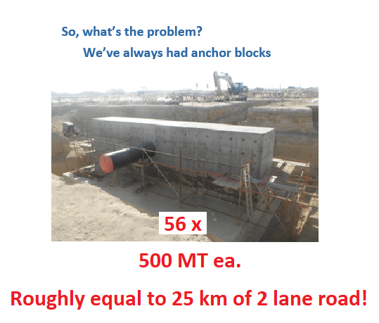
Well yes you can build large anchor blocks. REDICULOUSLY LARGE ANCHOR BLOCKS! The petroleum facilities of the mideast are full of them. Big ones. Pyramid size ones! Thank SaudiAramco for that. I think I understand why the Egyptians built them and my take away was their prime objective was not to anchor pipe. My theory is that pipe stress engineers, note as opposed to pipe flexibility engineers, today use them because the computer model slides off the paper if they don't have one. Caesar blows up. If Caesar didn't require at least one anchor to make the math work, most all anchors would magically disappear. Why do you need an anchor at 150? The best way to design pipes for lowest stress is to iterate anchor locations. Start with some relatively benign anchor configuration, anchors far away from equipment in the middle of a long pipe segment, maybe in the middle of a loop, maybe not. Find points along the pipe where movement is as near to zero as possible, then move the anchors to those locations and see if stress went up or down. If it went up, do the opposite while removing as many anchors as you can. Repeat until stresses drop to acceptable levels. Get a piece of 12 ga copper wire and make a physical analog model to help you to visualize the cause-effect relationships.

Picture from a presentation I did at the 2012 Abu Dhabi Pipeline Summit about how NOT to design pipe anchors.
This is what a 500 Metric Ton Anchor Block looks like. Now picture 56 of these things!
I just happen to think that this is the ultimate antithesis of good pipe design.
achor_blocks_uur0n0.png

P.S. I hate looking at pipe stress tables, especially in Kilonewtons per mm2 or something. The occasional isometric view is better. I can visualize the deflections in my sleep.

“What I told you was true ... from a certain point of view.” - Obi-Wan Kenobi, "Return of the Jedi"
 
I thought this was a pipe being placed within a casing, not 100m of a integrally welded annular/double wall pipe. That would certaily be difficult to do at that high op temperature, if not impossible. Why welded, double walled?

“What I told you was true ... from a certain point of view.” - Obi-Wan Kenobi, "Return of the Jedi"
 
Hello Axle,

Thank you so much for replying. I can't believe the picture, would never have imagined that big an anchor block, can understand that pipe size but that block is huge. I feel really dwarfed in the industry to be honest in these early stages of the career.

Find points along the pipe where movement is as near to zero as possible, then move the anchors to those locations and see if stress went up or down. If it went up, do the opposite while removing as many anchors as you can.
Yes, thank you for the recommendation. I did move the pipe support at different locations, changed other support behaviors and got a good stress relieve at anchor points. Will remember this.

I thought this was a pipe being placed within a casing, not 100m of a integrally welded annular/double wall pipe. That would certainly be difficult to do at that high op temperature, if not impossible. Why welded, double walled?
it is centralized in an encasing pipe( because of Site and legal requirements for that site) and I have supported it all along that length with spider centralizers. I input that support behavior as limit stops in the pipe stress model as I didn't know any other better way to do it with the knowledge I have. As the encasing pipe is jacked into the ground, I thought I can put limit stops , limiting the movement in the 2 coordinates and that may mimic the centralisers. Can use the limit stop loads from the software later on to design the supports as well.

Thank you so much for your gracious input. Learned a lot.
 
Thanks for the feedback. Glad you are honestly taking the opportunity to learn different approaches to solving pipe stress problems. Try to learn how to avoid those huge anchors that were the result of extremely bad pipeline layout. It was large diameter, thick wall and very straight, leading right into the center of the plant without any turns, loops or other flexibility inducing geometry. To make matters worse, the pig receiver was located there in the center of the plant too, which needed almost as large a barrier to stop any chance of a run-away pig from flying into the process equipment!

The spiders might be more accurately modeled as simple guides. They don't usually have much axial restraint capability.

“What I told you was true ... from a certain point of view.” - Obi-Wan Kenobi, "Return of the Jedi"
 
Status
Not open for further replies.
Back
Top