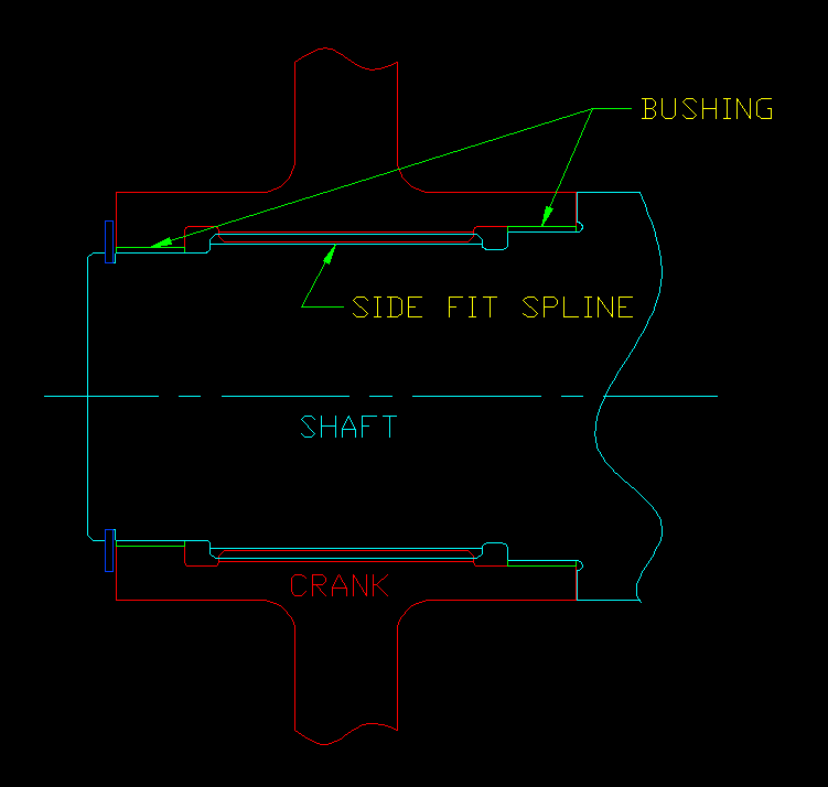
I am checking a calculation for the design of some splined joints as follows:
-Involute fillet root side fit splines
-Externally splined items are simply-supported shafts with the splines on cantilevered ends
-Internally splined items are bell cranks on each end with approximately quarter-turn rotation
-Loading is torque plus side force due to connected linkage rods: high load, low speed, low cycle, not fully-reversing
-Materials are nonferrous and ductile and are immersed in saltwater
-Size, weight, and cost are less important than schedule, so conservative hand methods are preferred over FEA
The calculation has changed hands a number of times in development and combines a hodge-podge of different analysis methods: Dudley from Machinery’s Handbook, the gear tooth from “beams of relatively great depth” in Roark, and shaft bending/torsion. I’m not convinced that it combines stresses correctly in all of the right places, or that the allowable stresses used are appropriate in all cases (some are based on my company’s traditional fractions of yield, and some make a leap from nonferrous materials to Dudley’s allowables for steel).
The design load is a very unlikely worst-case over 50% greater than what should ever be experienced in operation. I believe that failure will be dominated by stress rather than wear, and fatigue is not a concern. My impression from researching is that this is an unusual application without much precedent in the literature. The best reference I’ve found so far is Volfson, “Stress Sources and Critical Stress Combinations for Splined Shaft,” which does a good job of describing the bending and torsion stresses and the load distribution between teeth, but punts to FEA for the tooth stresses.
My general question is what design guidance the community recommends for this situation. I also have some specific questions:
1. Does analysis of spline tooth stresses typically neglect torsional shear components beyond the minor diameter?
2. What approaches other than Volfson have been used for distributing tooth loads due to side force?
3. Dudley’s S3 for the internal spline is “tensile stress due to the tangential force at the pitch line causing bending of the teeth.” I interpret this as a radial normal stress component (tooth bending) because there’s no factor to account for hub thickness (if it were hub bending). The other two components, S1 and S2, are clearly circumferential stresses (due to radial and centrifugal loading). This would be a state of biaxial stress, but Dudley adds all three directly, which doesn’t make sense to me. Am I misinterpreting the direction of S3, or is there a failure theory where principal stresses add, or am I missing something else entirely?
Thank you in advance for any input you can offer.

