Eng-Tips is the largest engineering community on the Internet

Intelligent Work Forums for Engineering Professionals

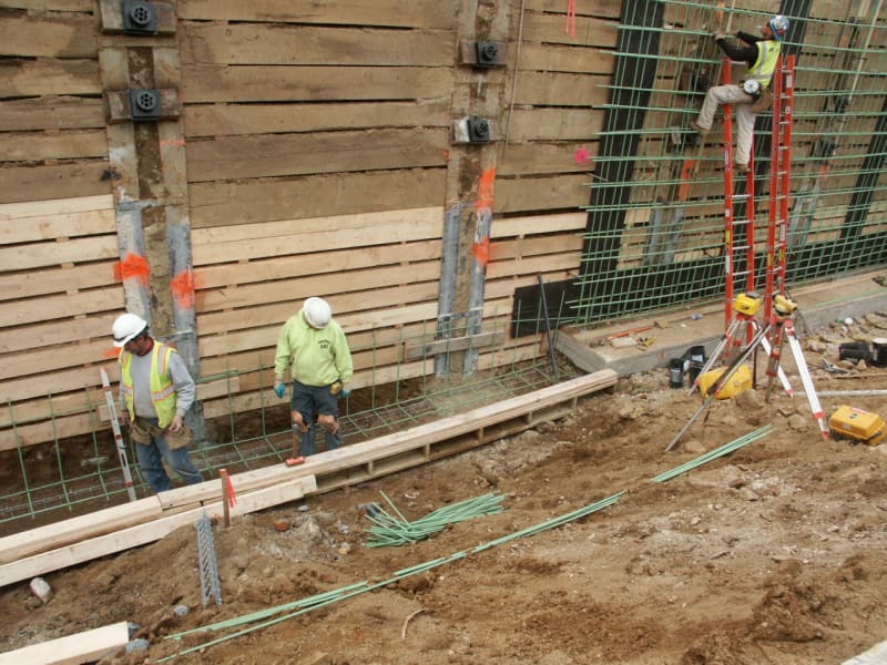
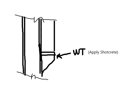
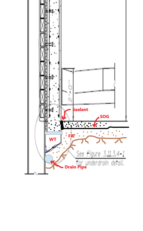
Design of shear studs connected to soldier pile walls/concrete facing 1

Status
Not open for further replies.

t230917

Structural
Apr 24, 2019
51
0
0
US
How do I go about designing the shear studs welded to soldier piles and connected to the concrete facing?

I referred to this thread: thread507-152519

But I need a little more information than was discussed in that thread.
 
Replies continue below

Recommended for you

Is this an excavation support, or permanent retaining wall? The design is exactly the same as for composite beam using effective width (concrete), transformed properties (Q, I), and finding shear flow (VQ/I).
 
This is a permanent retaining wall. I understand the procedure for concrete deck on steel beams, but unable to make the corresponding calculations for the soldier pile wall. Is there a guide that I can follow? AASHTO does not have anything for this, nor does the California Shoring Manual or any other state DOT manuals.
 
Don't over think. Simply lay the wall down horizontally, isn't it a continuous concrete deck on steel beams with linearly varying loads?
 
Is the concrete panel front face? If so, maybe you should consider add walers between the soldier beams to reduce the panel force demand, for durability concern too.
 
I do hope there is better detail for the drain pipe.

I was thinking adding structural shapes, which will be more reliable than wood lagging. Note if the concrete panel does not bear on footing, then you need to distribute its weight to the studs. Through this arrangement, the stud will subject to combined shear (due tp shear flow and panel weight) and tension (end reaction due to soil pressure), the allowable stress of stud will be reduced.
 
retired13, why would you ever want to use "structural shapes" instead of wood lagging? These types of permanent, anchored and cantilevered, non-gravity, soldier beam retaining walls use temporary (but left-in-place) wood lagging boards which laterally support the soil prior to installation of the permanent facing which is usually cast-in-place or shotcreted, reinforced concrete, precast concrete panels, or CMU's which can be attached to the soldier beams by various methods.
PICT1630_vyxap0.jpg


I don't know how long the wood will remain in good shape, but I know structural shape can stay a long time. From structural point of view, structural beams enable the concrete to be designed as two way plate, rather than one way beam element. Some saving can be achieved.
 
The wood lagging, treated or not, will lose its strength over time but it will not deteriorate enough to create any voids or problems behind the wall. The wood lagging, or your "structural shape" lagging, does not need to last any longer than the time it takes to install the final permanent facing.

 
Actually I don't know why we are even worried about the lagging, it will be there for excavation support, but it shall not be considered in the design of the concrete wall. Without horizontal waler beam, the panel has to be designed as one way slab, otherwise, it can be designed as two way slab. But after all, one way design maybe having less headaches construction-wise.

 
retired13 said:
I was thinking adding structural shapes, which will be more reliable than wood lagging.

retired13 said:
Actually I don't know why we are even worried about the lagging,

retired13, "we" aren't worried about the lagging. You brought up the lagging when you mentioned that "I was thinking adding structural shapes, which will be more reliable than wood lagging."

 
Yes, there is a better detail for the drain pipe; and the concrete facing rests on a concrete drilled shaft.

I have designed the facing as a one way slab, per the DOT manual.
 
Try to keep the concrete drilled shaft to a minimum diameter. You may still need a simple work pad under the facing, between soldier beams, in order to set your wall forms and account for any sloped grade along the wall. I would try to keep the weight of the facing off the concreted soldier beam embeddment length. A big cost is drilling the holes for the soldier beams, especially if there is rock to be drilled. The smaller the hole, the cheaper the wall.

 
retired13, I may be wrong but I assume that the concrete encased, embedded portion of the soldier beam below the bottom of the facing is what is being referred to as the drilled shaft. PennDOT refers to this as a drilled shaft or caisson. I do not think (but may be wrong) that there are additional drilled shafts, other than the soldier beams, that will support the facing. If there were more drilled shafts, they would interfere with the drain pipe shown in the sketch provided by t230917.

 
Suggested detail. (This approach ties the panels and soldier beams as an integral unit, thus settles uniformly, if any)

s_cfvt8a.png
 
Status
Not open for further replies.
Back
Top