Yes, there is only 1 drilled shaft that encases the soldier pile and supports the facing as well.
Thank you @retired13for the details as well. They will help.
To get back to the shear studs, I understand that it is a continuous concrete deck on steel beams with linearly varying loads. I have designed the concrete facing. Should the next step be to get the shear on the supports (soldier piles), i.e. V and multiply it with the transformed/composite properties "Q" and divide by the composite moment of inertia to get the shear flow?
Yes. Draw shear and tension diagram along the height of the composite section, the trail select size for shear stud. Note that the stud will subject to strength reduction due to combined shear and tension.
So, I found the shear flow. I multiplied it by 12" to get the shear per foot of the wall. I calculated Qr=phisc*Qn to get the strength of the shear studs.
Is this it? How do I get the max. and min. pitch?
For a 12" section of the wall, I am getting a shear of 8.21 kips, and the strength of the individual shear studs as 21.04 kips. Is that reasonable?
What equation you were using to calculate the shear flow? It is simpler to use f = VQ/I (ignore b at the denominator), so the result is force per inch in direction of the longitudinal axis (kips/in/width). Then, s = capacity (kips)/shear flow (kips/in). In your case, assume the calculation is correct, s = 21.04/8.21 = 2.56" - too close, try larger stud with 2 in a row to getting better result.
The thing that draw my attention is the statement - "I multiplied it by 12" to get the shear per foot of the wall. Let's think about, if the demand is only 8.21 kips within one foot distance, then 21.04 capacity is way beyond the demand, correct? In such a case, you shall reduce the capacity (select a smaller stud) to get into a more reasonable spacing.
Let's start from the beginning, what is the spacing of the steel beam? Your V shall equal to the reaction at the base, 8 kips seems too small. For example, a wall 10' height with 40 psf lateral load, and a tributary width of 10', R = 0.04*!10^2/2)*10 = 20 kips at the base, then V = 20 kips, which is to be used for stud design Please double check your load.
For per foot of soil behind the wall:
Surcharge pressure = 0.25*0.47 = 0.1175 klf/ft
Soil pressure at bottom = 0.12*13.25*0.47 = 0.7473 klf/ft
Force due to surcharge = 0.1175*13.25 = 1.56 k/ft
Force due to soil = 0.7473*13.25/2 = 4.95 k/ft
Total force at bottom of the cantilever beam = 1.56+4.95 = 6.51 k/ft
For 12' beam spacing, with 1.1 multiplier:
R = 6.51*12*1.1 = 85.9 kips, say 86 kips
Shear flow f = 86*209/5359 = 3.35 k/in
For Qr = 21.04 kips, spacing of studs, s = 21.04/3.35 = 6.28" ---> use 1 stud @12", or 2 studs @ 12".
Per the calculation, you can use 1 stud @3" from the bottom, then place the studs every 6" until the space can be lengthened (the shear force diminishes upward).
One important force to be included in your calculation - tension, due to soil pressure pushes the wall away from the support beam. The stud capacity will be reduced for the combined effects.
Note, the resulting spacing is for one stud, but if you use 2 studs in parallel, you have doubled the strength by a factor of 2, so the spacing can be lengthened for the same factor. (21k/6" = 42k/12" = 3.5k/in)
The calculation of tension force is slightly different than the reaction for shear flow. t/bolt = unit load strip*span length/2,
(t = Wi*L/2), as shown on the sketch below.
So, does the tension in the unit load strip = 0.1175 klf/ft+0.7473 klf.ft = 0.86 klf/ft; and we multiply this with the span length of 12 feet to get t=0.86*12 = 10.38 k/ft?
Does the total Qr then get reduced from 21.04 kips to 21.04-10.38 = 10.66 kips?
Another related question: Do we need to consider the weight of the concrete panel as a load that needs to be resisted by the shear studs?
Also, I have taken the Q and I as composite properties: do these need to be only the pile properties since we are not looking for composite action?
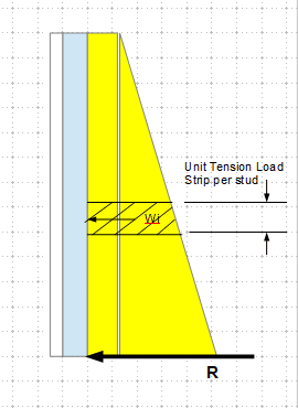
The calculation of tension is treating the wall panel as horizontal beam supported by the steel beams, and find the reaction. For example, for 1' strip from the bottom:
p[sub]13.25[/sub] = 0.7473+0.1175 = 0.8648
p[sub]12.25[/sub] = 0.6909+0.1175 = 0.8084
Wi = (0.8648+0.8084)/2 = 0.8066 ((note, intensity of Wi reduces from bottom up)
t = 0.8066*12 = 9.68 kips
With the obtained f & t, go to AISC J3.7 to determine the anchor strength for combined tension and shear in bearing type connection.
For your latter question, yes, the panel weight needs to be considered. I suggest to have continuous footing under the panel to transfer the weight directly into ground, to reduce the chance that over load the steel beams. Otherwise, you have to add the weight to the shear flow for connector design.
Yes, without design as a composite, your wall panel wouldn't be stand still. A floor slab can be designed either as composite, or non-composite; however, flip the slab-beam upside down in hanging ceiling-like manner, then the only choice will be composite. When in doubt, just ask "is the connection between the panel and the beam is necessary for the system to function properly?" Hope this helps.