Eng-Tips is the largest engineering community on the Internet

Intelligent Work Forums for Engineering Professionals

Design standards for shaft flats (D-shafts) 9

Status
Not open for further replies.

aaansari97

Mechanical
Aug 1, 2021
11
0
0
PK
Hi everyone!

I'm designing a mechanism that makes use of shafts. I have two questions:

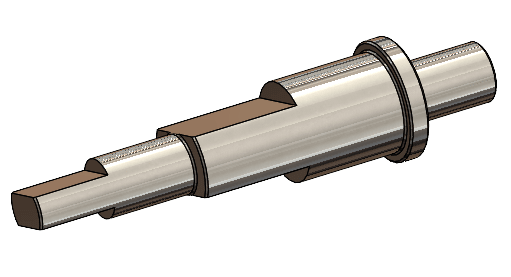
1.We are locking a 45 T, 0.5M gear in place on a dia 4 mm shaft using two flats (180 degrees apart) on the shaft and two setscrews. The torque is ~120mN.mm and we have already tested out this arrangement on a prototype.

My questions is if 2 flats 90 degrees apart are better than 2 flats 180 degrees apart? Our very experienced design consultant wants to go with the former (2 flats 90 degrees apart). Are there any standards which dictate how many flats, their depth and width, and their angular spacing there should be? The only informative literature I have found is from Misumi ( but this doesn't help us much.

Any leads will be appreciated.

2. My FEA and hand calculations tell me that the shafts are safe enough if made in 6061-T6 as compared to SS304 or SS316. In fact, 6061-T6 is safer for static load conditions. I know that steels are generally used for shafts but again are there other factors (such as fatigue considerations etc.) that I am missing?

Thanks!

Shaft_Design_sbii7w.png
 
Replies continue below

Recommended for you

Why not use keyways? That way you may have sufficient strength to use SS304/SS316.

Did you find any information in Machinery's Handbook? or Machine design books?

For 2-Fatigue will be major concern for the shaft you shown since there are sharp changes. If you have already done the calculations, then ignore this comment. Otherwise you need consider the material which is fatigue proof-steel. (At least for infinite life stress/endurance limit/fatigue limit).
 
I have been designing and repairing factory mechanisms for 45 years, large and small, high speed and low, high torque and low, continuous and intermittent, reversing and non-reversing. I have never yet, never, seen a flatted shaft work well for very long. It doesn't matter how many flats, where they are, whether you use setscrews or some other method of connection, even d-shaped hub bores. I came to this conclusion a few years ago, and since then I won't let any flatted shaft arrangement be put into use with my name on it. You're asking for trouble, and sooner or later, you will get it. And the end users at some point in the future will replace the flatted shaft with some better arrangement, while they curse the un-named engineer that first created it.

With a little more information I could suggest other more successful approaches.
 
Hi aaanari197

From a manufacturing point of view I would say that two flats at 180 degrees apart would be the easiest to produce and measure from an inspection point of view.
I cannot see any advantage in two flats at 90 degrees would have over two flats at 180 degrees maybe you should ask your most experienced designer to qualify his preference.
I have never seen any standards documenting what you are asking for. You will have to consider fatigue on this shaft if it sees cyclic loading during operation but your post doesn’t tell us what the shaft is used for.

“Do not worry about your problems with mathematics, I assure you mine are far greater.” Albert Einstein
 
Standards with dimensions for various drive connections on shafts are MSS SP-101 and ISO 5211. These standards are for valve.

Two things to consider. The torque capacity of the connection shape and the required length of engagement to prevent crushing of the corners transmitting the torque.

For the 2 surface at 90 deg apart, machining the shaft is not a problem, but how do you make the coupling that connects to it? Also think about teh required length of engagement since you may not drive equally on two surfaces. Most likely you will be driving on only one corner until it crushes enough for the second corner to engage. Also, not sure how fast you intend to shaft to spin, but the 2 at 90 deg shape is an unbalanced load.
 
Al will have a lower fatigue limit than SS.
And with Al there is no 'safe lifetime load' because the fatigue curves don't flatten out.
Fatigue critical Al parts are designed for a give number of cycles, and this number is rarely above thousands of cycles.
Don't let someone decide to use 303 in place of 304. The free machining grades have crap for properties.

= = = = = = = = = = = = = = = = = = = =
P.E. Metallurgy, consulting work welcomed
 
I would start over and use a standard clamp or drive feature. Set screws are usually relegated to alignment and assembly purposes bc they do poorly against torque, vibration, and thermal cycling. Assembly techs will also amaze you with the myriad of quality issues they can create with set screws.
 
I join the rest of the commenters who say that set screws aren't meant to transmit torque.

I've never done it myself, but I read in multiple places that it's a no-no.

Set screws on shafts are meant to fix things axially when there are no significant axial forces present. They are not meant to transmit torque or resist force.

Use a clamp or a taper lock bushing to transmit torque if a keyed connection is not possible.
 
Thanks, everyone!

Unfortunately, our assembly is pretty small and since we cannot use a keyed connection, I think we will have to go with a set-screw & flat combination. I understand the concerns here regarding setscrews, but I am intending to make a prototype with this arrangement and set it to a high-frequency test to see if the setscrews loosen over time or if there is a loss in motion. I am also thinking of applying a thread locker to the setscrews.

But I do appreciate that this arrangement should not be present in a high torque system.

On a separate note, we have a pin reciprocating in a slot. I've attached an image of the slotted rocker here. In a previous arrangement, we observed a lot of wear in the slot. We are now considering two options:
1. Using an SS304 slotted rocker and nitride it to 50 HRC. The dia 3mm pin would be a hardened (HRC50) SS416 dowel pin
2. Hardening an SS416 slotted rocker to HRC50. The dia 3mm pin would be a hardened (HRC50) SS416 dowel pin

Forces normal to the slot are in the order of 40-50 N max.

My questions are as follows:
1. Should the pin be harder than the slotted rocker or vice versa? I think the pin will get worn faster and should be harder. Is my understanding correct?
2. We have material constraints and have to remain within stainless steels. What options would you people suggest to minimize wear (including or other than the 2 listed above)?

Any leads would be appreciated.

Thanks!
Ahmed

Rocker_omvl4q.png
 
Hi aaansari97

Wear is a minefield in terms of variables however I would suggest that you make the easiest part to replace the one that wears

“Do not worry about your problems with mathematics, I assure you mine are far greater.” Albert Einstein
 
IMHO, if the slot is wearing faster than pin then you need to make slot and pin both of material which is good wear resistant (400 series). Besides the pin diameter of 3mm seems too low for any long duration friction. It will get consumed fast. Main tread off between 300 and 400 series is the corrosion resistance.
 
Hi,

desertfox said:
Wear is a minefield in terms of variables however I would suggest that you make the easiest part to replace the one that wears

This makes sense. We're using off-the-shelf dowel pins and those would be easiest to replace. Thanks!

NRP99 said:
Corrosion is not a really big concern since these parts should never really get in contact with water. These are meant to be safeguarded against corrosion under general ambient humidity.

I guess that SS416 would better suit our hardness requirement.

Thanks!
 
Is that part in the picture the one that connects to your D shaft?

From what I see, that thing could be modified to form a clamp which would be far better for transmitting torque than a set screw.
 
Look at the arrangement of setscrews on small pillow block beatings . Either single, or two at 90° or some "optimized" angle. Never 180°. The goal is to clamp the shaft (HARD) against a broad ~ 180° support surface on the hub ID.


Two setscrews at 180 simply have the setscrews fighting (push-of-war?) each other, or possibly even having the shaft held floating centered in the hub bore teetering on the setscrew tips, munching away at the shaft and themselves with every load reversal or variation.
Either result is structurally useless.
A setscrew arranged more tangentially rolling the shaft hard against the flats in the same direction of the operating load would be better.
Split the hub to allow clamping the shaft would be better.
A ringfedder type tapered bushing would be better.
A commercial taper lock type bushhing would he better. I did not check to see if such devices are available for 4 mm shafts.

A Ø .5M 19" gear on a mere Ø4 mm shaft ?
What kind of radial and tangential/torsional loads are you expecting?
Where are the bearings located on the shaft?
 
As far as the flat positioning, if they are at 180 degrees then the section modulus will be quite a bit lower in one orientation. So maybe not so efficient from a stress standpoint. I'm guessing you are not turning very fast so balance is not an issue. Manufacturing wise I'd don't see any more difficulty putting the flats at 90 degrees vs 180 degrees. Performance wise I don't see any torque handling differences. I do see that more of the shaft stuff I buy have the screws at 90 degrees so I might be missing something there.

Seems like a big gear on a small shaft (sorry about units, about 20" diameter gear on a .16" diameter shaft).
 
For the rocker there are a few choices.
I would go with hard pins, 410, 420, or even 17-4PH should be available. You could even use 440 If you can get them easily.
The rocker does need to be harder than standard 304. While nitride is one option the soft core material doesn't support the hard surface very well.
You could look at 301LN or Nitronic 40 (another 200 grade). They will work harden a lot under wear and are very resistant to galling.
If you go with a 400 grade make the rocker HRC 45-50 and keep the pin about 5 points lower.
Using different materials always helps reduce galling and can help wear as well.

= = = = = = = = = = = = = = = = = = = =
P.E. Metallurgy, consulting work welcomed
 
"Look at the arrangement of setscrews on small pillow block beatings"

Those screws do not transmit torque, and lock the inner race to the shaft and serve their purely locational purpose well.
 
Thanks again!

I get the discontent regarding the setscrews here and will try a splined connection next time.

As for the gear size, it's 45 teeth with a 0.5 module (pitch diameter is 22.5 mm). Working load is bidirectional and about 120mN.m (not much) that's why we were going with the setscrew arrangement. Also, we have another similar mechanism that works pretty well with similar loads.

EdStainless said:
For the rocker there are a few choices.
I would go with hard pins, 410, 420, or even 17-4PH should be available. You could even use 440 If you can get them easily.
The rocker does need to be harder than standard 304. While nitride is one option the soft core material doesn't support the hard surface very well.
You could look at 301LN or Nitronic 40 (another 200 grade). They will work harden a lot under wear and are very resistant to galling.
If you go with a 400 grade make the rocker HRC 45-50 and keep the pin about 5 points lower.
Using different materials always helps reduce galling and can help wear as well.

EdStainless, do you mean that we keep the pin slightly less harder than the rocker? Doesn't this conflict with your first statement that the rocker need not be harder than SS304?

Thanks!

 
Status
Not open for further replies.
Back
Top