aaansari97
Mechanical
Hi everyone!
I'm designing a mechanism that makes use of shafts. I have two questions:
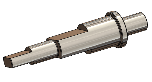
1.We are locking a 45 T, 0.5M gear in place on a dia 4 mm shaft using two flats (180 degrees apart) on the shaft and two setscrews. The torque is ~120mN.mm and we have already tested out this arrangement on a prototype.
My questions is if 2 flats 90 degrees apart are better than 2 flats 180 degrees apart? Our very experienced design consultant wants to go with the former (2 flats 90 degrees apart). Are there any standards which dictate how many flats, their depth and width, and their angular spacing there should be? The only informative literature I have found is from Misumi ( but this doesn't help us much.
Any leads will be appreciated.
2. My FEA and hand calculations tell me that the shafts are safe enough if made in 6061-T6 as compared to SS304 or SS316. In fact, 6061-T6 is safer for static load conditions. I know that steels are generally used for shafts but again are there other factors (such as fatigue considerations etc.) that I am missing?
Thanks!

