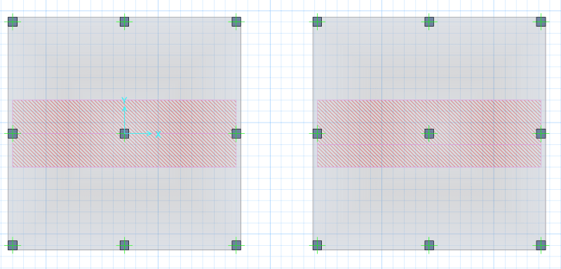
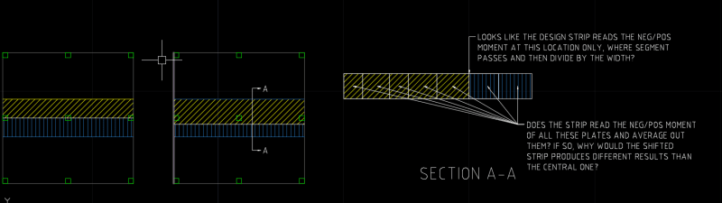
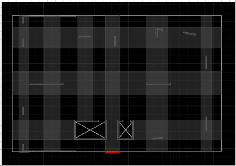
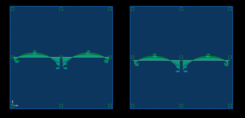
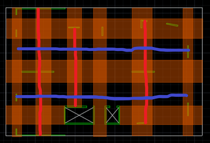
I have a flat slab with irregular supports. I want the reinforcement to follow the global x & y direction instead of principal moment direction.
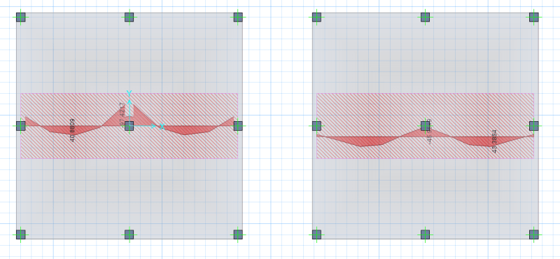
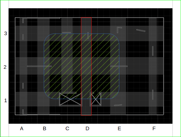
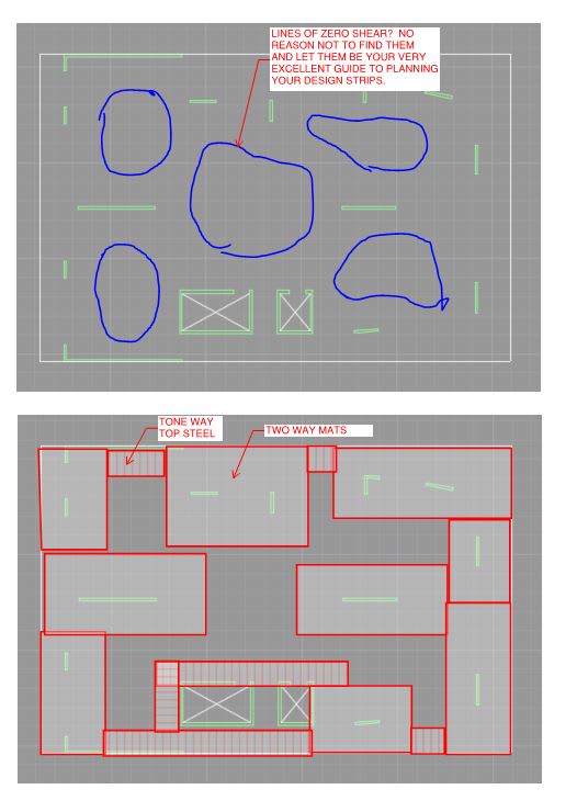
So I am thinking having design strips passing each support but I find it very hard to arrange the design strips. Can anyone share your thoughts or if you can, provide your design strips say latitude for this one?
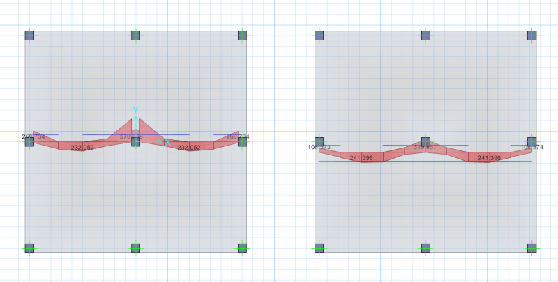
As these short walls have two ends, do I run two design strips through both ends? Can anyone please share some example of this kind of structure?
Thank you.
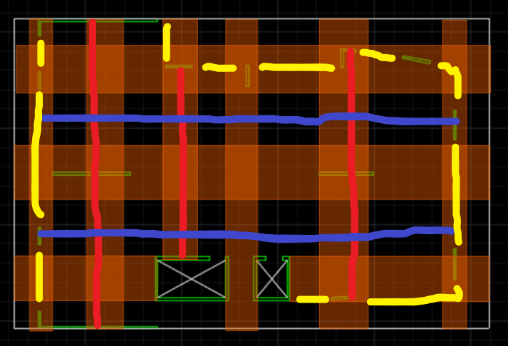
So I am thinking having design strips passing each support but I find it very hard to arrange the design strips. Can anyone share your thoughts or if you can, provide your design strips say latitude for this one?
As these short walls have two ends, do I run two design strips through both ends? Can anyone please share some example of this kind of structure?
Thank you.