Eng-Tips is the largest engineering community on the Internet

Intelligent Work Forums for Engineering Professionals

Design Strip For Irregular Flat Slab? 4

Status
Not open for further replies.

J189

Agricultural
Oct 7, 2019
29
0
0
AU
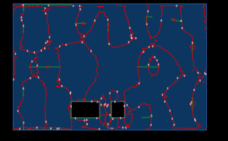
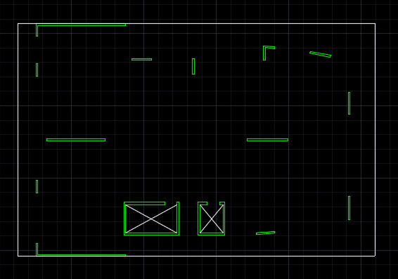
I have a flat slab with irregular supports. I want the reinforcement to follow the global x & y direction instead of principal moment direction.
So I am thinking having design strips passing each support but I find it very hard to arrange the design strips. Can anyone share your thoughts or if you can, provide your design strips say latitude for this one?

As these short walls have two ends, do I run two design strips through both ends? Can anyone please share some example of this kind of structure?

Thank you.

1221_oravik.png
 
Replies continue below

Recommended for you

Off topic - but I'm using Google Chrome and it seems embedded images are not showing up (ie can't see these plots). Any ideas how to fix this? Is it a company firewall issue?

 
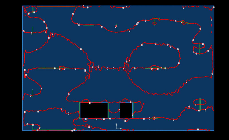
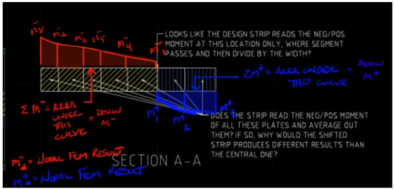
Going back to your section A-A this is how I understand the design M- and M+ should be gathered from the cross section FEM results. When you have changes of sign different programs take different approaches to how enveloping of the design moment on the cross section is handled, may be worth taking your post with Section A-A screenshot and asking SAFE's tech support how their program handles those situations.

Capture_b0jagm.jpg


For your check model with the offset strip I would definitely reach out to SAFE as to why the offset strip produces a lower design moment at the column, this seems wrong to me based on my understanding of how the design moments should be generated.

My Personal Open Source Structural Applications:

Open Source Structural GitHub Group:
 
celt83 said:
...when you have changes of sign different programs take different approaches to how enveloping of the design moment on the cross section is handled
.

If any program is unable to report and design to the positive and negative areas independently, I'd say that program is pretty seriously flawed. As rapt pointed out, you'll just wind u losing track of some of the moments required for equilibrium. And, as will be obvious when we get into the zero shear method (thanks for the prelim work BTW) strip definitions on complex layouts are rarely anywhere near perfect.

Trenno said:
Off topic - but I'm using Google Chrome and it seems embedded images are not showing up (ie can't see these plots). Any ideas how to fix this? Is it a company firewall issue?

Chrome works for me but I've got supper lax IT.
 
Celt83 said:
Are you saying you would expect the computer program to automatically sub-divide that cross section A-A into two smaller design sections, one containing all the positive moment gradient and the other containing all the negative moment gradient?

More or less. I wouldn't expect anything as fancy as subdivision to be required though. I know that you're really a robot, AI, or cyborg so let's try this:

SUM_M_POS = 0
SUM_M_NEG = 0
i = 1

FOR EACH ELEMENT i CONTRIBUTING TO AGGREGATED STRIP DESIGN ACTION(s):

IF Mi > 0 THEN

SUM_M_POS = SUM_M_POS + Mi

END IF

IF Mi < 0 THEN

SUM_M_NEG = SUM_M_NEG + Mi

END IF

i = i + 1

END FOR
 
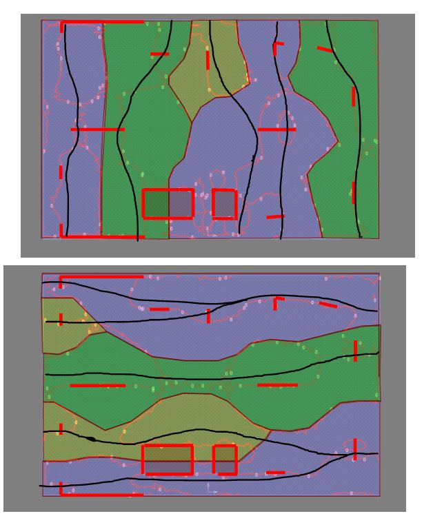
This is just step #1 using the diagrams that Celt83 has kindly provided. I've got family in town this week so I'll have to pace myself.

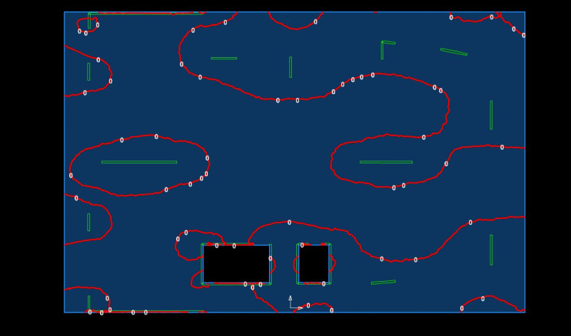
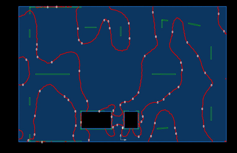
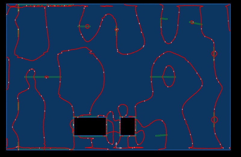
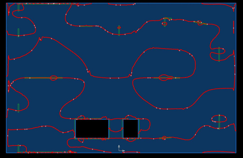
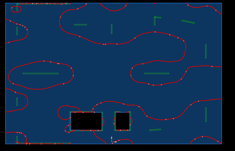
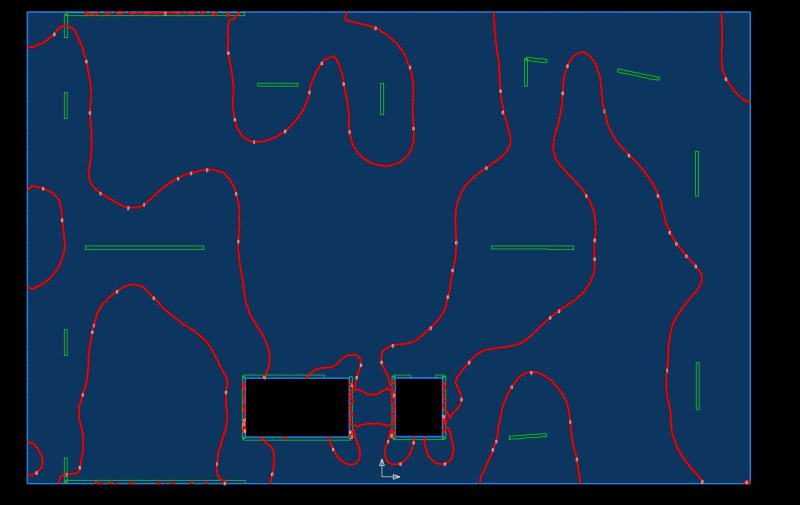
For now, I've just allowed the slab to tell us its story of complexity and shame without passing any superfluous judgment on orthogonality, conductibility, or sweep. Some zero shear lines have been taken as natural bands of stiffness; others as natural points of demarcation between strips which include both the the column strip and half of a middle strip on each side. Essentially, this is the strip disposition that I would anticipate giving a reasonably accurate estimate of tributary load to the columns if the the two orthogonal strip directions were overlaid.

C01_kj8cjf.jpg
 

Thank you. Strip force from Ram Concept looks reasonable. Don't know why SAFE gives different results. So does that mean in Ram Concept you can simply place the span segments in ortho directions with reasonable strip widths despite the layout of supports instead of running from support to support with skew angle (I am not familiar with skew angle concept BTW) although it may be not cost effective?
 

Thank you very much KootK. I will definitely have a look at '0 shear lines' and come back if I have more doubts!
 
Yeah you are right. I tried to use this method and find something bit weird, even if I set the averaging width to 5meters it still shows much more reinforcement required at top than I used strip method with smaller widths.
 
I have an open dialog going with the RAM folks on their enveloping procedure, I'm not certain that design segments with both significant positive and negative moment are being considered in the way that Kootk outlined, based on some section auditing and my understanding of the manual seems its looking at the dominant moment sign only, but I'm not not positive on that so waiting on feedback from them as to what is going on in the backend.

As Rapt noted if you just rely on straight cross section equilibrium you could end up with a net 0 design moment, which while mathematically correct could lead to an unsafe design. Think this is a larger issue for PT in the US market since we have convinced ourselves that full width design strips are adequate but column layouts are becoming much more irregular leading to sign overlaps in strips with significant areas of sign change. For mild slabs this can be avoided or limited by adjusting column and middle strip bounds utilizing the 0 moment plots.

CSI has decent tech support as well reach out to them and see what they have to say about design strip boundaries covering areas of positive and negative moment.

My Personal Open Source Structural Applications:

Open Source Structural GitHub Group:
 
Slightly off topic, but concerning design column and middle strips, what would be the consequences of a middle strip which did not have sufficient reinforcement? Say the reinforcement was not installed correctly on site in the middle strip location.
 
Celt83,

Fortunately many countries do not accept the full panel design width logic.

Secondly, it is only accepted in its original form if the prestress layout provides a proper balanced load pattern which provides a load path to the supports.

- Equally spaced tendons in both directions is not acceptable.
- As support layouts become more random, it becomes harder to satisfy this. But it still needs to be satisfied!
- It becomes more and more necessary to include Mxy moments in design as support patterns become more random. Some software still does not include this in design actions by default even though they calculate it in the analysis. It is NOT Compatibility Torsion and cannot be ignored.
- With transfer concentrated loads, the pattern has to provide a load path from the applied point loads to the supports. Equally spaced in even one direction does not satisfy this. A "band" of tendons is required on the concentrated load line as well as the support line and the different groups of tendons need to act together to provide a load path to the supports.
 
Rapt:
Thank you for the additional info. The Mxy moment we always consider although it took some effort to drive that home. Full width design strips always seemed weird to me especially so if the slab has drop panels.

Any books or papers you could recommend reading to get myself better educated?

My Personal Open Source Structural Applications:

Open Source Structural GitHub Group:
 
You are right about Drop Panels. I have commented on this whole topic many times on different threads. You could try to find them if you want the detail.

The logic is purely a PTI/ACI development so you will not find a lot in other codes or text books from other countries. Unfortunately, the text books on it are from USA and give examples with drop panels, including the PTI manual (not sure if it is in current releases as I have not wasted my money on one for about 40 years). It does not say a lot about the authors. The logic elsewhere is the same as RC flat slab logic using column/middle strips in both directions and laying out the tendons and reinforceemnt in a 2way pattern. So no special books are required!

The original concept was that with unbonded prestress you could not easily weave the tendons so they came up with the idea of a one way banded/distributed tendon pattern that provided a logical load balance but did not match the elastic moment pattern and only in flat plate slabs, no drop panels.

So the ultimate condition required a lot of redistribution and is basically a yield line solution without a yield line analysis. This actually works ok with regular column grids with flat plate slabs. The problem with this is that as the column pattern becomes more random, the elastic analysis you are getting from FEM differs by more and more from the Yield Line result you are actually trying to achieve. Averaging the results of an elastic analysis with random column positioning is not consistent with a possible yield line solution.

Also, unbonded prestress required a lot of extra bonded reinforcement to make the slab act as a flexural slab once cracking occurred. Without that and without bond of the tendons the slab went into catenery.

This extra reinforcement, top over the supports in both directions and a bottom mat in the slab panels made assisted the slab in acting as a flat slab should.

But the idea at the start was to keep the stresses low at service (basically in compression) so that the slab was uncracked at service, so there was no redistribution at service so deflection performance was no adversely affected. If you look at the British TR43 Version 1 which used this method for BS8110, it required a tension limit in negative moment zones of 0, i.e. fully in compression, based on the average stress in the panel!

Then people started doing it with bonded prestress and also allowing much higher stresses as we would in a partially prestressed slab. But bonded prestress design codes do not require this extra reinforcement so designers using the logic were missing out on the benefits of the extra reinforcement as the codes assumed proper 2way column middle strip logic is being used with bonded tendons so this extra reinforcement was not mentioned in other codes. Banded/distributed slabs require this extra reinforcement also!
 
Status
Not open for further replies.
Back
Top