Hello everybody,
I'm a mechanical design engineer in a aerospace company in Europe. First post here, hope everybody is well during this uncertain times.
Well, as the post subject suggest I'm having some issues in my company with other departments (WHHAAAAAAAT?!?!? REALLY??!?!? NEVER HEARD OF THAT!!!).
The problems are of course related to tolerance(and more), few examples:
- we receive some parts from a supplier and it is not up to spec. Quality/production in conjuction with the supplier of the part says that tolerances are too tight (drawing is wrong) and must be modified so we can accept the parts.
It usually goes "we need this part right now! It's in our interest to accept that part but you need to change the drawing for that".
Well the problem is that the supplier oversold its capacity at the beginning and he said that could keep those tolerances "no problem", had the drawings in his hands for months and now (when the parts are being checked) he's saying that we cannot pretend such tight tolerances. I trusted him and did not ask to put it in writing so there's no paper trail.
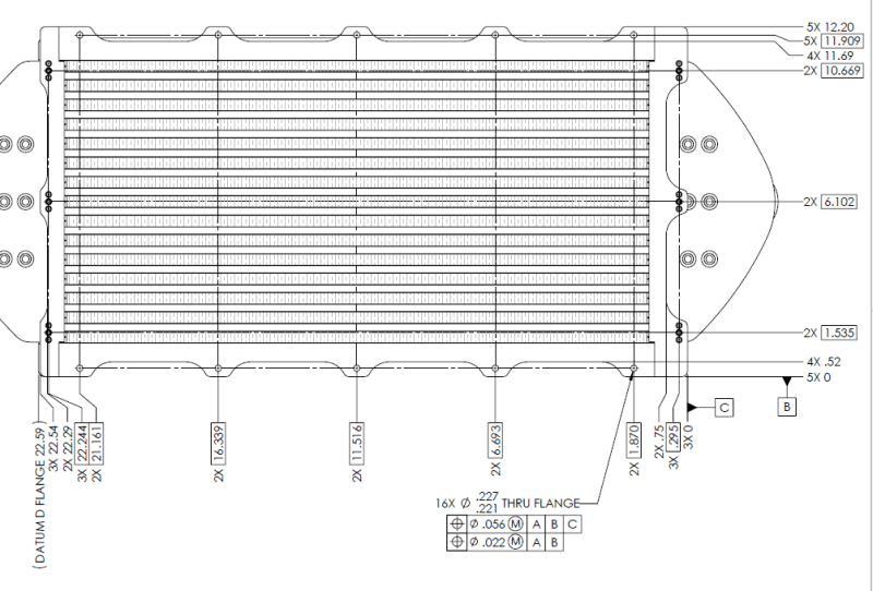
We already changed the drawings a couple of times (enlarged holes to relax hole location tolerance or changed DATUMS) and it didn't work, there's always something wrong with the holes pattern location.
The problem is not even this particular supplier but it is a constant even with internal production. It seems that this is the "modus operandi" in this company, we release the drawings, nobody says anything for months and then when QC check the parts and they are out of spec ----> "the drawings are wrong", "we must change the drawings so we can accept the parts".
- Quality doesn't seem to follow best practice or norms in checking the parts. Typical example: when checking hole location with the CMM they use the edges of the part as the zero. I told them multiple times that's not at all best practice because the edges might not be straight or perpendicular to each other and they have to use a metrology square or other metrology tools to "simulate" the DATUMS but they simply say "that's all theoretical, the edge is straight". , to me it doesn' make any sense, and the theoretical thing is that the edge is straight..... Am I wrong on this? We receive several custom made parts (heat exchangers, fans etc..) for hundreds of thousands of dollars but QC doesn't care about ASME/ISO standard clearly stated on the drawing by the manufacturer.
After a recent exchange with them where they tried to apply the general tolerance to a basic dimension (?) I've come to the conclusion that they have no idea about modern GD&T and all the nice CMMs and tools we have are just the proverbial lipstick on a pig. To compound this impression they always ask me to use the plus or minus method to locate holes and other feature instead of the GD&T way, recently they increasingly ask drawing modification to put as many dimensions "as reference" as possible because "you don't need to check them".
When I confront them trying to explain all the above they became aggressive and basically say that I cannot teach them how to work.
Has anybody had a similar experience? I'm thinking going to upper management to present the situation, I don't think they are fully aware. I've been in this company a couple of years now and my impression is that they are on a downward trajectory regarding all the technical aspects.
Thanks in advance.
I'm a mechanical design engineer in a aerospace company in Europe. First post here, hope everybody is well during this uncertain times.
Well, as the post subject suggest I'm having some issues in my company with other departments (WHHAAAAAAAT?!?!? REALLY??!?!? NEVER HEARD OF THAT!!!).
The problems are of course related to tolerance(and more), few examples:
- we receive some parts from a supplier and it is not up to spec. Quality/production in conjuction with the supplier of the part says that tolerances are too tight (drawing is wrong) and must be modified so we can accept the parts.
It usually goes "we need this part right now! It's in our interest to accept that part but you need to change the drawing for that".
Well the problem is that the supplier oversold its capacity at the beginning and he said that could keep those tolerances "no problem", had the drawings in his hands for months and now (when the parts are being checked) he's saying that we cannot pretend such tight tolerances. I trusted him and did not ask to put it in writing so there's no paper trail.
We already changed the drawings a couple of times (enlarged holes to relax hole location tolerance or changed DATUMS) and it didn't work, there's always something wrong with the holes pattern location.
The problem is not even this particular supplier but it is a constant even with internal production. It seems that this is the "modus operandi" in this company, we release the drawings, nobody says anything for months and then when QC check the parts and they are out of spec ----> "the drawings are wrong", "we must change the drawings so we can accept the parts".
- Quality doesn't seem to follow best practice or norms in checking the parts. Typical example: when checking hole location with the CMM they use the edges of the part as the zero. I told them multiple times that's not at all best practice because the edges might not be straight or perpendicular to each other and they have to use a metrology square or other metrology tools to "simulate" the DATUMS but they simply say "that's all theoretical, the edge is straight". , to me it doesn' make any sense, and the theoretical thing is that the edge is straight..... Am I wrong on this? We receive several custom made parts (heat exchangers, fans etc..) for hundreds of thousands of dollars but QC doesn't care about ASME/ISO standard clearly stated on the drawing by the manufacturer.
After a recent exchange with them where they tried to apply the general tolerance to a basic dimension (?) I've come to the conclusion that they have no idea about modern GD&T and all the nice CMMs and tools we have are just the proverbial lipstick on a pig. To compound this impression they always ask me to use the plus or minus method to locate holes and other feature instead of the GD&T way, recently they increasingly ask drawing modification to put as many dimensions "as reference" as possible because "you don't need to check them".
When I confront them trying to explain all the above they became aggressive and basically say that I cannot teach them how to work.
Has anybody had a similar experience? I'm thinking going to upper management to present the situation, I don't think they are fully aware. I've been in this company a couple of years now and my impression is that they are on a downward trajectory regarding all the technical aspects.
Thanks in advance.

![[rednose]](/data/assets/smilies/rednose.gif "[rednose] [rednose]") (Whether or not you check the dimension has nothing to do with that)
(Whether or not you check the dimension has nothing to do with that)