Continue to Site

Eng-Tips is the largest engineering community on the Internet

Intelligent Work Forums for Engineering Professionals

  • Congratulations SSS148 on being selected by the Eng-Tips community for having the most helpful posts in the forums last week. Way to Go!

Designing a beam as doubly reinforced though it could be done Single reinforced 18

Status
Not open for further replies.

NewbieInSE

Structural
Dec 19, 2019
234
Hello Engineers,
I'll elaborate it. Say i have a concrete beam having some dimensions, its moment capacity for singly reinforced criteria is 400 kips-ft, say. Moment induced from loads in that beam at the certain location is say 330 kips-ft. It means i can design it as singly reinforced, and say reinforcement requirement is 2.5 in^2 as singly reinforced section.

My question is can i design that section of 330 kip-ft moment requirement, as a doubly reinforced section requiring bottom reinf. say 2.3 in^2, and at top say from calculation .6 in^2 or anything. I think it is possible, considering bottom reinforcement is yielding, but want to know in depth.

I'm actually asking it for existing structural members, which contain less reinforcement (bottom) than required when considered singly reinforced, but contain some top reinforcement which maybe could help in forming doubly action.
Thanks.
 
Replies continue below

Recommended for you

my beams very often have "compression face" reinforcement that either reaches 50% or even full tensile yield

I am scratching my head trying to figure out the phenomenon that flexural reinforcement on both tension and compression faces have fully yielded. It can occur in tension member only, or doesn't it?
 
retired13 said:
I am scratching my head trying to figure out the phenomenon that flexural reinforcement on both tension and compression faces have fully yielded. It can occur in tension member only, or doesn't it?

Yielding the compression reinforcement in a member subjected to flexure alone requires having a neutral axis low enough in the member to produce a strain of at least 0.002 at the level of the compression reinforcement. Practically speaking, I suspect that requires some combination of the following in most cases:

1) A tension only rebar design that would be getting close to the balanced / over-reinforced condition which usually implies a deep-ish compression block and, therefore, a low-ish neutral axis. It's tough for an under-reinforce beam to reach 0.002 strain hear the compression face.

2) A quantity of compression steel that is less than the quantity of tension steel. If you imagine a hypothetical case with equal reinforcement and in which no concrete participates in compression, your neutral axis would be at the mid-height between the top and bottom steel and both reinforcing groups would yield simultaneously when their respective strains hit 0.002. Add back in some concrete compression block and that's only going to shift your neutral axis upwards from this condition.
 
KootK,
I understood that Lomarandil thinks his compression steel is yielded in tension, thus retired13's confusion, in this case.
 
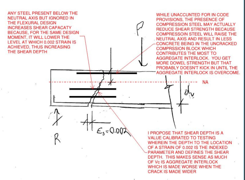
I have some thoughts to offer on the interplay between flexural reinforcement depth and shear depth. Please refer to the sketch below.

SOME PRELIMINARIES

1) Note that, in reinforced shear design design, we take Vc in the cracked concrete member to be the same value as Vc in the uncracked concrete member. That's a bit weird when you ponder it as one case is elastic-ish and the other is cracked/plastic.

2) If you look around at the various shear provisions for slabs, beams, plain concrete, and prestressed concrete, you will often find alternate definitions of the shear depth that are independent of the location of the flexural reinforcement. 0.8h and things like that.

3) In my mind, #1 + #2 = shear depth is a parameter that is indexed to shear testing rather than being a "pure" variable in the physics / mechanics of materials sense that it might be under elastic stress conditions. The cracked, plastic condition is very different animal.

MY CONCLUSIONS

4) Rebar located below the neutral axis but not considered in the flexural design will not reduce the shear depth. In fact, it will increase it per the sketch below as, for the same design moment, it will lower the location of 0.002 tensile strain.

5) A far more robust definition of shear depth would be "the depth at which tensile strain reaches 0.002". I believe that such a definition eliminates most of the sources of confusion that arise from the usual code definition of shear depth.

c01_uzgqhy.jpg
 
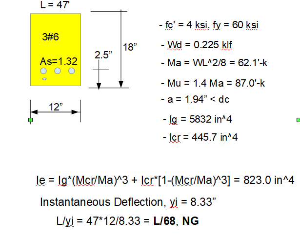
An example problem to demonstrate the effect of a beam with too shallow a compression block (a < dc).

Problem statement - a 47' long simply supported, singly reinforced beam subjects to self weight alone. Find whether it satisfies both strength and service criteria. (Please double check my calculation for mistakes.)

Strength Check: Vu = 7 kips, ØVc = 8.8 kips; Mu = 87'-k, ØMn = 86.3'-k, say ok.

e_gr45on.png
 
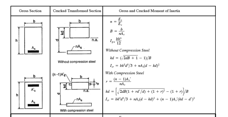
Equations for Icr calculation.

q_rx8ofi.png
 
What may I ask are you trying to demonstrate/say/prove with this example?
 
Amazing how these discussions develop sometimes! Most of this is second year concrete design at university.

RE Compression reinforcement for flexure (or any reinforcement for that matter for flexure), simplified strength formulae assume both compression and tension steel are at yield. But the application of this logic is limited because that is not always the case.

That requires that certain limits be placed on steel depths and neutral axis depths.

For tension steel to be yielded, the neutral axis depth must be below the balanced depth. And that is assuming that all of the steel is at the extreme tension face. If there is side face steel then it may not be at yield depending on its depth below the neutral axis.

For compression reinforcement to yield in compression, the neutral axis depth has to be deeper than a certain value. Rectangular stress blocks for concrete do not change this as they are simply a simplified method of calculating the compression force in the concrete, they have nothing to do with the steel strain and stress. This will depend on the compression face strain, .003 in ACI, but .0035 reducing with increasing concrete strength top .0028 in Eurocode, and the yield strain of the reinforcement and the quantity of tension reinforcement which controls the neutral axis depth.

For shallow members, it is often hard to achieve compression yield in compression face reinforcment. In all cases a minimum amount of tension reinforcement is required. It is possible for the compression face reinforcement to be in tension, for shallow lightly reinforced members especially and where increased cover is provided.

Otherwise, the calculations have to be based on the strain at each steel layer, tension and compression.

Because most designers do not want to do this, they ignore the normally very small benefit from compression reinforcement.

RE effective depth dv (Canadian Code) for shear they have adopted the ACI logic for prestressed members limiting effective depth d to .8D and a minimum value, Technically it should be the depth to the tension force under the ultimate loading, not the ultimate flexure condition. The Canadian model actually bases this on the point at which reinforcement reaches yield, not even the real ultimate condition.
But as I understand it from the Canadians who did all of this research, they did no testing to justify the .8D figure. They just used the ACI value. For normal RC members, it makes no difference, but for members with reinforcement over the depth of the tension zone it can be significant. Also when PT is involved, it uses the centroid of area of the different steels which is completely illogical when one of the steel types is 4 times the strength of another.
They agree that technically it should be the depth of the tension force under ultimate loading.


Agent666,

If you are asking me, you didn't read the opening statement, which I stated clearly the purpose/cause it to serve. With a compression block such small, the beam faired badly and fail service criteria, though it satisfies the strength requirement. But there is a catch, that the example has violated an important rule in design, I think some one would get it sooner or later. Let's see.
 
retired13 said:
If you are asking me, you didn't read the opening statement, which I stated clearly the purpose/cause it to serve.

You stated the purpose it was supposed to serve, but it doesn't serve that purpose. The deflection is not excessive because the depth of the NA is to small, it is excessive because the section is not stiff enough for the span and load. If you halved the strength of the concrete the ULS neutral axis would be well below the cover depth, but it would not reduce the deflection under SLS loads, it would increase it.

Doug Jenkins
Interactive Design Services
 
IDS,

You still don't know what you are arguing about. After hardbutmild posted the stress-strain diagram on 25 APR 20 22:35, I posted several comments to point out the invalidity/absurdity of that odd condition, that is, the NA located above the supposedly compression steel. The reactions/responses I received were not very positive/receptive, thus I addressed it again on 26 APR 20 02:34:

Secondly, IMO, the neutral axis shall not be allowed to be above, even near, the compression steel, since the concrete is not confined, the nominal compressive stress can not be sustained/achieved. Although the so called code requirement on balanced strain condition is satisfied, failure is a sure thing, so something definitely needs to be done to meet the demand - further increase compression capacity and maintain moment capacity, preferably increase beam depth.

Then on 26 APR 20 03:08, I questioned:

I am also curios that will that beam satisfies deflection/service criteria, with cracked section properties, not to mention long term effect.

Without receiving any response, I created the example just to point out the fact that there was something fundamentally wrong that led to hardbumild posted condition. I am glad that it draws your attention. As your response serves as the confirmation of my persist concerns and comments, but you probably did not realize it.

Yes, in real design, it (NA above compression steel) should not happen, and would not occur, since any engineer with basic training will begin his/her design with a beam depth selected in accordance to code recommended span/depth ratio, thus, in normal circumstance the deflection will not be excessive, because the implied adequacy in section properties and rigidity. But, it seems sometimes people are not taking that check (span/depth ratio) seriously as an important first step in design, then weird situation does occur.

 
retired13,

You should just give up when you are behind. Your example is nonsensical, much too shallow for the span, and the neutral axis location has little to do with it.
 
Hokie66,

I don't quite understand why I was "behind".

I purposely made the example up to demonstrate what is the consequence when compression block is too small, which should never occur. As you correctly pointed out, the smallness of that block was caused by not having adequate depth from the beginning, the mistake rendered the stress-strain diagram drawn for that condition, and the calculation, all waste efforts. A lot of discussions were made un-necessarily after my comments made on 26 APR 20 02:34, which was replicated on comments above.

But you are right, I've stated all I've to say. It's time to stop this non-sense. Thanks.
 
rapt said:
For compression reinforcement to yield in compression, the neutral axis depth has to be deeper than a certain value. Rectangular stress blocks for concrete do not change this as they are simply a simplified method of calculating the compression force in the concrete, they have nothing to do with the steel strain and stress. This will depend on the compression face strain, .003 in ACI...

The particular shape assumed for the compression block may not affect top bar strain but the depth of the compression block, whatever its shape, absolutely does since that depth is an indirect measure of the depth to the neutral axis.
 
NewbieInSE,

Sorry to have sidetracked your thread. The linked paper shows how the moment capacity is calculated for doubly reinforced flexural member. Wish it helps. Link
 
Kootk,

I was making the point that just because the total depth of the compression block is assumed to be at constant stress does not mean that the steel will be at the equivalent steel stress allowing for Es/Ec. The diagram above was at least misleading on this showing a rectangular stress block.The stress in the steel is controlled by the strain in the section, not the assumed simplified stress pattern in the concrete compression zone and is dependent on its depth from the compression face and the depth of the neutral axis.

Retired13,
The only code rule that controls the minimum depth of the neutral axis, indirectly, is the minimum reinforcement rule. In shallow members and T sections it will often result in a neutral axis depth above the compression face reinforcement for lightly reinforced members, especially if someone uses the ACI318 1.33Mu limit for minimum reinforcement.
BS8110 used to have a sort of a limit of .05D but for beams less than 1m deep, that still resulted in a neutral axis depth within the cover concrete with minimum reinforcement. No other code I know of has any limit.
 
rapt said:
BS8110 used to have a sort of a limit of .05D but for beams less than 1m deep, that still resulted in a neutral axis depth within the cover concrete with minimum reinforcement. No other code I know of has any limit.

Didn't BS have a provision that z <= 0,95d, meaning that the compressive force position is at 0,05d away from compressed edge? Usually this distance is between 0,35x and 0,42x (x is length of compressed part). This would mean that compressed part is around 0,12d and this usually means that compression side reinforcement is in compression, right? Of course, the question of it yielding is related to the strain.

On additional note, I'm sad to see people argue in this thread.
 
rapt,

I agree there is no code limit on NA above the top face reinforcement, but that will be back fired by the service criteria (the Ieff is just too small). I remember in T-beam, the NA can be very close to the top steel, but I'd never allowed it to go above. IMO, the safe way to start a design, is trying to stick to the span/depth ratio as close as possible. It might require deeper section, but will be rewarded with less deflection headaches (I don't know the implied "no need for deflection check" clause is still in the code or not). Sometimes, the increase of the beam depth is not possible due to physical limitations, then adding another beam is unavoidable.
 
Status
Not open for further replies.

Part and Inventory Search

Sponsor