Continue to Site

Eng-Tips is the largest engineering community on the Internet

Intelligent Work Forums for Engineering Professionals

  • Congratulations SSS148 on being selected by the Eng-Tips community for having the most helpful posts in the forums last week. Way to Go!

Designing footings for wood shear walls

Status
Not open for further replies.

Andy_S

Structural
May 11, 2022
2
Any input on methodology for designing footings for wood shear walls? Typically I've seen the walls supported by a thickened slab, but is there a way to quantify the width needed for a given soil bearing (assuming it is NOT carrying gravity loads)? Alternatively, if we use spread footings at each end of the wall (for uplift and bearing), can the middle portion of wall just sit on the slab on grade?
 
Replies continue below

Recommended for you

What negates deep beam behavior if the various interface connections can develop the shear flow?
Capture3_zxjekm.jpg


I'm making a thing: (It's no Kootware and it will probably break but it's alive!)
 
I could see from a global Strut-Tie approach how you end up with a sub-truss within the concrete portion:
Capture3_s6ttwm.jpg


I'm making a thing: (It's no Kootware and it will probably break but it's alive!)
 
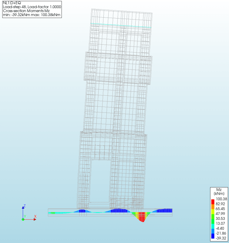
This reminds me a little of strip footing moments below precast walls. Below is an model that includes all the wall dowels and an interface representing the grout (zero tensile). No question there is a moment in the footing, but not all design for that in my experience.

footing_ub4ymx.png
 
Cool model Brad.

How did you model the grout for taking shear in the model? Is it allowed to develop in-plane shear like Celt has mention which is critical to the deep beam idea?

Why is there negative moment at the end of your footing?

S&T -
 
ST, I have an overhead door on both sides of the panel, so I modeled the footing to the CL where I could assign a restraint. This is a non-linear model and I have a material model that allows one to set the tensile capacity of the interface. The grout does have shear capacity. This was a unique assignment where they need to keep the weight of the panel to a certain value.
 
Celt83 said:
What negates deep beam behavior if the various interface connections can develop the shear flow?

Relative vertical stiffness between the shear wall above and the foundation below. The only way for the grade beam to be braced by the wall above when a flexural crack forms is if the the grade beam is so flexible relative to the wall above that you actually develop a prying mechanism. And that would, of course, be utterly heinous. It would also be highly unlikely in the case of wood panel shear owing to that pathetic shear flexibility that I mentioned earlier.

As a mental experiment, consider the case below where the deep beam action would brace the grade beam: a slender steel beam as the grade beam. Ick.

C01_fjmxew.png
 
I'm coming around:
(Robot 2023 model attached)
7-3/4" CLT panel over 8" CIP Stem Wall. The CLT is closer in stiffness to the concrete than a Gyp. Sheathed Panel would be and its already showing signs of the normal force being dominant down in the CIP elements. The model has vertical spring releases along the bottom panel joints allowing them to separate. This is certainly a simplified model compared to Brad805 as it's only based on shell behaviors.
Capture3_equlet.jpg


Robot 2023 File: Link
Stiffness Matrix Basis for the CLT: Link

I'm making a thing: (It's no Kootware and it will probably break but it's alive!)
 
I realized perhaps we haven't been talking about exactly the same thing.

In the context of lateral load only I agree with KootK the shear wall separates from the cast-in-place (CIP) stem wall. Then everything bends independently upwards so the CIP portion has it's own bending moment.

I have been trying to merge with the case where the wall is fully loaded + Lateral Load resulting in no net uplift or partial vertical loading. In these cases there is no separation of the two elements and the resulting soil pressure in the rigid base model is trapezoidal and results in bending along the length of the system. In this case I think the deep beam analogy has some validity as the curvature of the CIP portion would be translated to the base of the wall above and the portion of bending resisted in the CIP is highly dependent on the stiffness of the wall panel above.

I'm making a thing: (It's no Kootware and it will probably break but it's alive!)
 
Status
Not open for further replies.

Part and Inventory Search

Sponsor