I'm not gonna talk to Belimo any time soon and their newer PICV have electronic flow meters that control the valve and they can show the flowrate in BAS. That obviously is the best!. Talk to your specific manufacturer about the valves you have.
you don't need to set the pressure setpoint to what the could requires. the system pressure gets measured at one point, all the coils are elsewhere and have different dP requirements. You need to determine at what system pressure you still have enough pressure at the coils. So if the system pressure is measured around the pump, it may be 20 psi, if it is somewhere int he system, it may be 15 psi. but your coil and valve may only require 7 psi.
In the past i used the mechanical PICV, i may swithc to using the electronic ones and will revise the below. Being able to "read" all the actual flow at once and in real time should simplify things. If yo manually measure with dP or dT, it will be less arcuate and yo need to move around the building to iterate.
Below is what I specify:
H. HYDRONIC FLOW BALANCING
I. Balance after system has been cleaned, flushed and all strainers and dirt separators are cleaned and all flow restrictions removed. Verify correct strainer screensize is installed. Verify all valves work correctly.
J. Measure flow of coils, boilers, heatpumps and other devices with pressure drop over device. Contractor shall install standard ¼” pressure taps as required.
K. For coils in air streams determine flow by measuring air flow, EAT, ELT, EWT, LWT, and heat balance method.
L. Correct for varying viscosity based on fluid temperature, glycol type and glycol %.
M. Total system flow cannot be measured by pressure gain over pumps.
N. Final water system measurements must be within the following range of specified gpm:
Heating flow rates: -5% to +10%
Cooling flow rates: -5% to +10%
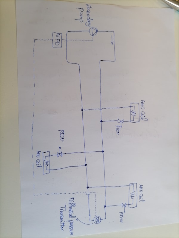
O. VARIABLE FLOW WITH PRESSURE INDEPENDENT CONTROL VALVES (PICV):
1. DETERMINE STATIC RESET SETPOINTS:
a. Operate Pump to maintain 50% of design pressure
b. Open all control valves 100%. Designer will provide information on diversity.
c. Measure all device flows and tabulate design flow vs. actual flow and determine the 5 critical zones that are at lowest % of design flow. Verify flow in critical zones is not deficient for other reasons (i.e. dirty strainer, wrong pressure-independent device installed).
d. If flow in critical zones is below design, increase system pressure setpoint. If all flows are at design flow, repeat above with lower pressure / pump speed
e. Re-iterate until the lowest pressure setpoint is found that still allows design flow in 5 critical zones. The final pressure is the actual maximum pressure and will be reported to Controls Contractor to set as maximum pressure for static pressure reset. The minimum pressure typically will be set at 25% of that.
2. VERIFY ZONE / DEVICE FLOW:
a. At upper static pressure reset pressure setpoint measure the flow in each device / zone. Note that if diversity was applied to determine the static pressure setpoint, some valves need to be closed to measure the flow in the other zones.
b. This is meant to determine if there are flow restrictions of the wrong type or size PICV is installed. If deviations are encountered, consult with engineer and manufacturer.
P. CONSTANT FLOW:
1. Operate pump at 50% speed.
2. Measure flow over device.
3. Adjust pump speed as required (or balancing valve if single speed pump)