Continue to Site

Eng-Tips is the largest engineering community on the Internet

Intelligent Work Forums for Engineering Professionals

  • Congratulations KootK on being selected by the Eng-Tips community for having the most helpful posts in the forums last week. Way to Go!

Determine right pressure setpoint 3

Status
Not open for further replies.

saeedplc

Electrical
Nov 27, 2021
126
Hi dear experts

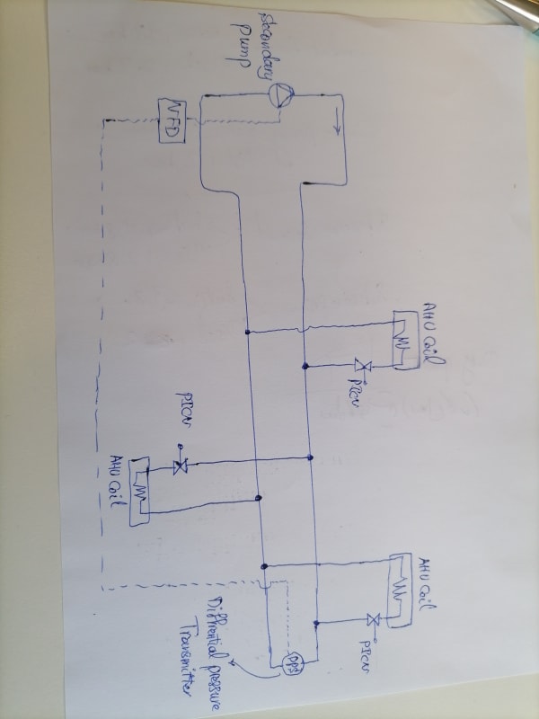
Could you please let me know how to get right diffrential pressure value in secondary loop of chilled water system supplying different terminal units?
A diffrential pressure transmitter has been installed in farthest unit and all units are equipped with pressure independent valves. a Vfd is controlling the secondary pump speed according to the pressure value.
i need to determine right pressure setpoint.
Your reply will be highly appreciated.
 
Replies continue below

Recommended for you

You should hire an HVAC guy before you screw this up.
 
At some point someone needs to have verified flow to determine that. It also depends on if you use regular, or pressure-independent valves. it also depends on if you have a feedback controlling the modulating valve (i.e. air temperature discharge sensor to control coil valve) or by an on/off control like unit heaters.

Google "static pressure reset" for further options to control.

It should be part of commissioning/balancing to determine this.
 
Thank you for the reply.
All coils are controlled wirh pressure independent valves.
Each valve is controlled (0 to 100 percent) by the feedback from supply duct temperature sensor on AHUs.
I have heard that for getting right setpoint of diffrential pressure transmitter at the most remote terminal unit all the picv valves should be opened and then increase speed of secondary pump by increasing frequency through vfd manually and measure pressure across coil and picv of most remote terminal and once right pressure has been obtained then consider that amount of pressure as setpoint pressure for secondary pump speed control in auto mode.
Is this method right or not? Please let me know more if any other thing needs to be take into account.
 
Most remote valve is pointless since that valve may only be 20% open. The critical path could be any of the paths at any given time. The old rule of "furthest" branch only held true for constant volume 3-way valve systems. Think about it, if the AHU next to the pump is at 100% valve, and all other are at 20%, the 100% AHU is the critical one. Or one at 50% halfway away..... there is no single critical path. the critical path is jsut a design value assuming full flow to all coils at the same time.

This isn't a static system, everything is dynamic and changes constantly. During balancing you need to determine minimum and maximum pressure and than based on valve positions the pump will aim to meet a point in between those extremes. If most (say 95%) valves are 99% open, the pump will maintain the maximum pressure point. If all valves are below that, it can meet lower setpoints. So your question should be: "what is this maximum and minimum pressure point?"
You actually can measure pressure around the pump, you get higher values (easier to measure) and faster reaction. With static pressure reset the system is more forgiving -if set up correctly.
 
Thank you so much for your valuable reply.

There is no doubt that you have much experience than me i just want to know where is my mistake.
As i mentined earlier all the valves are pressure independent valve and most of AHUs are the same in aspect of capacity.
If i open all the valves and measure the pressure of last terminal unit of AHU and it become right after adjusting the secondary pump speed then certainly the pressure at valves near the pumps will be higher and the picv valves get their minimum delta pressure to works properly.
If other valves become close according to the working condition then speed of the pumps decrease and adjust the pressure to the setpoint that we put on the system.
As i know if picv valves have pressure across them more than minimum that is mentioned in their data then they work properly.
You are right about critical valves and maybe some systems have some terminal units far away from system or some different vslves with different demand.
What i am saying is that after finding the right pressure setpoint at farthest unit it should be ensured that critical valves or other units get right pressure to work.
Needless to say, because last unit get minimum pressure to work others unit most probably gets higher pressure and there should not be any worry.
I have seen some systems that have some tees far away from pump and for compensating pressure instead of increasing pressure of system use tertiary pump.

Your opinion is highly appreciated to share.

Thanks.
 
Can you please sketch this out so we know what location you're looking at.

Remember - More details = better answers
Also: If you get a response it's polite to respond to it.
 
1644575040248_pkdt7b.jpg
 
what options do you have to estiamte the flow for the valves? Pressure is hard, since the PICV typically give you the same flow from 5-50psi (look at specs!). So that doesn't tell you much. that's the whole point, they give you the flow INDEPENDENT of pressure as long as they have the minimum pressure. The problem is, they also work perfectly fine with too much pressure, which cost you pump power.

Can you measure flow over the coil by measuring coil differential pressure or dT? You have to look at the coil specs and it also depends on airflow. So this is not easy or straight forward. Can you measure pressure drop over the PICV (and no strainer or anything else)? You kind of have to find the pump pressure needed to just barely have enough flow... the problem is to find out if you have enough flow.

So my first advice is to find out what options you have to estimate what flow you have. the PICV i know don't have a port to measure flow. they have ports to measure pressure drop, but that isn't related to flow like a balancing valve. You could try to set the system pressure so that all PICV still have 5psi (or what the manufacturer says is the minimum) differential pressure.

Actually I have a project in design and i will talk to the Belimo rep since they had changed their valves since last time I bought them. Maybe look at the PICV specs and talk to manufacturer o learn what they offer.
 
Thank you so much

Dear EnergyProfessional we have some points to measure the picv and coil pressures so please confirm the below method:

1.open all picv valves to get the maximum flow from secondary pump(increase the pump speed until get a right pressure across the picv and coil)
2.Measure the pressure across the picv and the coils that are farthest from the pump
3.if the pressure on the picv and the coil was right(minimum pressure across picv and right pressure across the coil according to nominal flow)
then add picv pressure to coil pressure and set this value as setpoint pressure of the secondary pump vfd drive

This is your kind of asking from the belimo may be they suggest a better way.

Regards,
 
I'm not gonna talk to Belimo any time soon and their newer PICV have electronic flow meters that control the valve and they can show the flowrate in BAS. That obviously is the best!. Talk to your specific manufacturer about the valves you have.

you don't need to set the pressure setpoint to what the could requires. the system pressure gets measured at one point, all the coils are elsewhere and have different dP requirements. You need to determine at what system pressure you still have enough pressure at the coils. So if the system pressure is measured around the pump, it may be 20 psi, if it is somewhere int he system, it may be 15 psi. but your coil and valve may only require 7 psi.

In the past i used the mechanical PICV, i may swithc to using the electronic ones and will revise the below. Being able to "read" all the actual flow at once and in real time should simplify things. If yo manually measure with dP or dT, it will be less arcuate and yo need to move around the building to iterate.

Below is what I specify:
H. HYDRONIC FLOW BALANCING
I. Balance after system has been cleaned, flushed and all strainers and dirt separators are cleaned and all flow restrictions removed. Verify correct strainer screensize is installed. Verify all valves work correctly.
J. Measure flow of coils, boilers, heatpumps and other devices with pressure drop over device. Contractor shall install standard ¼” pressure taps as required.
K. For coils in air streams determine flow by measuring air flow, EAT, ELT, EWT, LWT, and heat balance method.
L. Correct for varying viscosity based on fluid temperature, glycol type and glycol %.
M. Total system flow cannot be measured by pressure gain over pumps.
N. Final water system measurements must be within the following range of specified gpm:
Heating flow rates: -5% to +10%
Cooling flow rates: -5% to +10%
O. VARIABLE FLOW WITH PRESSURE INDEPENDENT CONTROL VALVES (PICV):
1. DETERMINE STATIC RESET SETPOINTS:
a. Operate Pump to maintain 50% of design pressure
b. Open all control valves 100%. Designer will provide information on diversity.
c. Measure all device flows and tabulate design flow vs. actual flow and determine the 5 critical zones that are at lowest % of design flow. Verify flow in critical zones is not deficient for other reasons (i.e. dirty strainer, wrong pressure-independent device installed).
d. If flow in critical zones is below design, increase system pressure setpoint. If all flows are at design flow, repeat above with lower pressure / pump speed
e. Re-iterate until the lowest pressure setpoint is found that still allows design flow in 5 critical zones. The final pressure is the actual maximum pressure and will be reported to Controls Contractor to set as maximum pressure for static pressure reset. The minimum pressure typically will be set at 25% of that.
2. VERIFY ZONE / DEVICE FLOW:
a. At upper static pressure reset pressure setpoint measure the flow in each device / zone. Note that if diversity was applied to determine the static pressure setpoint, some valves need to be closed to measure the flow in the other zones.
b. This is meant to determine if there are flow restrictions of the wrong type or size PICV is installed. If deviations are encountered, consult with engineer and manufacturer.
P. CONSTANT FLOW:
1. Operate pump at 50% speed.
2. Measure flow over device.
3. Adjust pump speed as required (or balancing valve if single speed pump)
 
Thank you so much for great your great reply.

Dear EnergyProfessional we are not going to use pressure reset method and only a fixed pressure is preferable so do you please confirm what i mentioned in my previous post to performing?

Thanks a lot.
 
If you don't do static pressure reset, it is the same procedure as determining the max pressure. the goal here is to get the max pressure as low as possible while still having enough flow in critical zones.

BTW, adding the reset-function doesn't require added hardware, only programming. That is a huge energy saving. Because the maximum pressure is the pressure you need at full load day, which isn't representative for 364 days of the year.
 
Just wanted to second what energyprofessional said. A pressure reset or trim and respond routine is the way to go.
 
Dear EnergyProffessional if i want to install diffrential pressure transmitter the proper place is near the coil or terminal unit that has most pressure drop and flow demand.If the farthest coil has low flow there may be low pressure drop and placing the sensor on that coil can cause low flow for high demand coil even those that are closer to the pump because the vfd controlling the pump get signal from the coil that has low pressure drop so it is completely depend on the design and location of the units around the site.
As a whole , the most demand unit or coil should be determined first according to flow and pressure drop then see if that coil pressure is provided the other coils specially those remote coils are getting enough pressure to work with nominal flow.
In this case the transmitter is installed but if the remote coil has highest pressure drop then best place for installing the transmitter is near this coil.
All my comments are based on using constant static pressue setpoint not setpoint reset method.
After setting the right pressure on the system then it dhould be confirmed that pressure on coils near the pumps is not higher than close off and maximum pressure of the pressure independent control valves(Picv)

Please confirm my understanding.

Regards,
 
Here is the thing, if your system has 2-way valves that modulate or are on/off, you have a variable flow system. Flow in all branches will depend on the load in time. So the critical path will change depending on operating conditions. If you had constant volume (i.e. 3-way valves), you would have a critical path that will be the same all the time.

Best you can do, is determine the critical path under the assumption all valves are 100% open. But this will be sub-optimal since that is not how the system operates in real life.

Your system is a constant volume system with SOME variable volume features. But not all variable flow features. so yo still need to control pressure like in a CV system.

I'm not quite sure if you plan to relocated the dP sensor, but that requires pipe work. it is easier to implement static pressure reset since that only is a programming work and is agnostic to where the sensor is located.

Close-off pressure of a PICV is extremely high (50 psi, or so). That is not what you control for. You need the design flow pressure (often 5psi, but check with manufacturer).

Look at the sensor spec. they are rated for the system pressure, often 50 or 100 psi. Measuring a 5psi or less differential pressure will be relatively inaccurate. If you have a % accurate sensor, that is 2psi on a 100 psi sensor. That's why I use them for around the pump where we have more pressure. Some are differential sensors and you pipe from both ends water to the sensor. Some are standalone sensors where you have 2 sensors directly in the pipes. While in theory the "farthest" location may be better, that is only the case with perfect sensors and not with real sensors.
 
You are completely right but although the critical path change depending on ghe load in time but i mean if all 2 way presuure independent valves that are modulating become open 100% and on that case measure pressure at farthest coil and it would be right then that pressure can be set as constant static pressure setpoint in the system. As i mentioned earlier to make sure other closer units to the pump gets right pressure measure some coils that have higher capacity.
This pressure is maintained by the vfd in all cases eirher in high or low load occasions. We have got the pressure setpoint in worst case when all the valves are open completely so there is no need to be worried at all regarding partial load or so on.
The vfd drive decrese and increase pump speed according to the diffrential pressure sensor so pump curve moves and we can get high power saving however i know pressure reset method brings higher energy saving compare to constant pressure setpoint but function of the system will not change.
I have not compared effeciency of these two method but i dont think there would be huge difference.
But about the picv valve i meant those coils or units closer to the pumps should not get pressure higher than their operational pressure because as you know much better than me that all picv valves have min and max pressure that guarantee they retain the flow irrespective of the main pressure fluctuations.

 
You have another problem to consider. PICV come in gpm-increments. So if your coil has a design flowrate of 31.5 gpm, you use a 40 gpm PICV and let the DAT sensor control the valve. the PICV is just like a fail-safe in this case. in case of a sensor failure, the flow isn't fully open, like going to 60 gpm, it will be inherently limited to 40 gpm (if that is the PICV). But if you try to set the pressure point and have the valve 100% open, you have too much flow, and hence too much pressure. I don't have a good solution for this. Without using static pressure reset it is iffy. I start to like more the PICV with electronic flowmeter.
 
I am sorry i dont get what you mean.
The picv valve has a rotary knob that enable user to adjust the coil maximum flow so the coil will not get overflow even in high pressure situation mostly in partial load of the system.
I meant measure coil pressure when all the picv valves of the system are opened 100% so if the pressure across the coil is compliance with the coil maximum flow and minimum pressure on the picv valve is provided then sum of the coil and picv valve pressure would be setpoint pressure of the system.
The setpoint pressure of the system should be at least sum of the coil pressure at full flow and the picv valve min pressure and if we have this amount of pressure across the critical terminal unit everything will be alright.
Regarding the sensors failure a good plc programmer or electrical engineer consider function of each component in the system and if any abnormal situation is recignized the system issue a fault.
This discussion is very helpful for me and thank you so much for sharing your ideas.
Please excuse me if i couldnt get your mean of previous statement.
 
I don't know what type of PICV you have. I can only speak to devices I have used and design with.

But you need some way to measure the flow and verify this still meets the design intent. You can measure flow by dT, or dP over a device. The problem with dP is, a coil has every low dP and you need the pressure ports. the problem with dT is, that also depends on airflow and temperature. Hard to control unpracticed. Before PICV thee were calibrated balancing valves that introduce a high pressuredrop and have curves to read the flow rate from that.
How to commission the system should be part of the design so that it is possible to actually verify flows with some method.

Really, static pressure reset is much easier to implement than all the things you have to do if you want to determine a "good" fixed pressure point. Or use PICV that measure the flow (hard to do after the fact when you already have PICVs))

Without static pressure reset you are driving a car at full throttle, and you regulate speed by applying the brake. With your fixed pressure setpoint you maybe improving this a bit by only applying 3/4 throttle, but you still waste energy most of the year and spend a lot of time on balancing to find out if the 3/4, 4/5 or 5/8 is the optimum. Use static pressure reset (and your throttle is at what is needed or only slightly above. With modern controls, static pressure reset is really easy to implement Easier than finding that pressure setpoint.
 
Status
Not open for further replies.

Part and Inventory Search

Sponsor