RealSaladsamurai
Mechanical
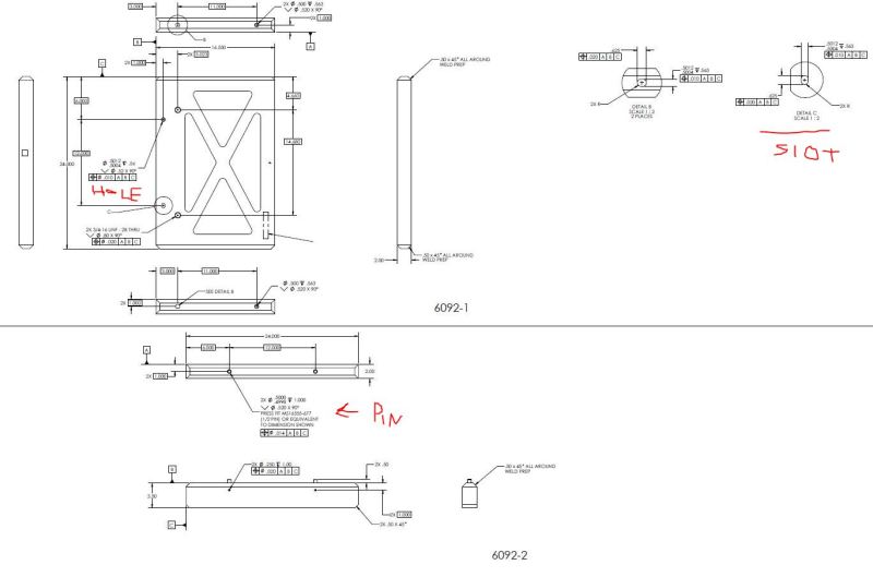
I trying to determine if the tolerances on a mechanical drawing make sense with respect to the part function. In the attached image There are two components that are to be welded together. One part has 2 dowels pins press fitted into it while the other part as a hole-slot pair. From my online searches, this seems to be a pretty common scenario. I just want to make sure that I am thinking about the stackup correctly.
I am thinking that in order to do the stackup I should use the fixed fastener formula. Typically, with a fixed fastener scenario, you have one part with the fastener tapped in and the other part has a thru hole. We do not have a thru hole, but instead have a blind hole for the dowel to slip-fit over. I am assuming that we can use the fixed fastener formula, where instead of using the thru hole part thickness P in equation below, we instead use the maximum height that the dowel pin can attain.
So the virtual condition of the fastener can be found by:
VC_F = F + T2*(1+2P/D)
where:
F = MMC diameter of dowel = .5003 (from MS16555-677)
T2 = tolerance of position of fastener = .014
P = max height of dowel pin above surface = .51 (default tolerance of .01 on .XX
D = min depth of pin in hole = .995 (which can't really happen at same time P as at worst case)
So I arrive at:
VC_F = .5003 + .014*(1+2*.51/.995) = .529
The virtual condition of the mating hole is given by
VC_H = H - T1
where:
H = MMC diameter of hole = .5004
T1 = positional tolerance of slip-fit hole = .010
So that:
VC_H = .4904
This would appear to be a big problem since the VC of the hole is .039 less than the VC of the fastener.
Is this the correct way to do this? I realize that the slot has a sloppy tolerance in one direction, but I am not taking advantage of this fact in my calculations. Can somebody help to clarify how I can incorporate this fact? I am not sure how to mathematically account for this "one-sided" aspect of the slot.
Thanks again for your help.
________________________
FEMAP v11.1.0
MSC Nastran v2013