Eng-Tips is the largest engineering community on the Internet

Intelligent Work Forums for Engineering Professionals

Determining Maximum Load for Flat Roof for Solar Panel Installation 2

Status
Not open for further replies.

BufordTJustice

Mechanical
May 19, 2004
26
0
0
US
Hello-

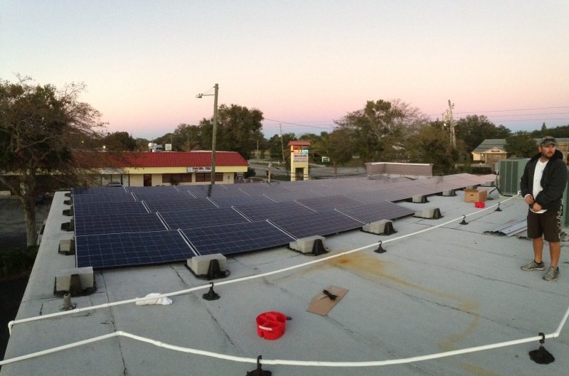
I have a flat roof onto which I am interested in installing some solar panel arrays. As I am in a high wind area (design is ~145 mph), I either need to penetrate the roof 50+ times to anchor the panel mounting rails, or use a ballasted system and avoid the penetrations altogether.

I am leaning towards the ballasted approach as it not only eliminates the cost of large number of roof penetrations but also the opportunities for leaks which will certainly become more likely with so many penetrations. The ballasted approach also removes uplift loads from being applied to the roof structure itself (as the ballast is sized accordingly to handle this).

In any case, the specifics of the roof are as follows----

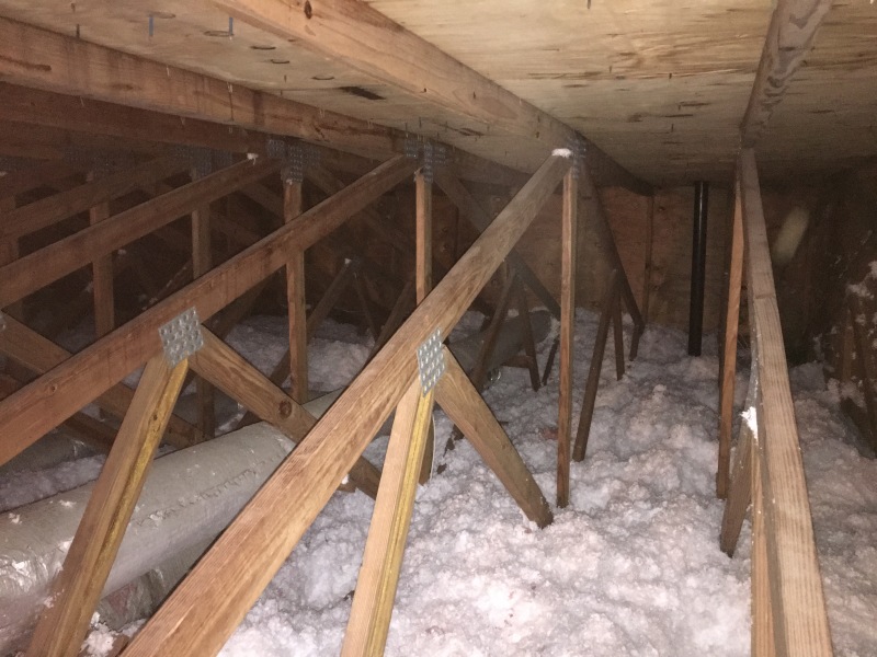
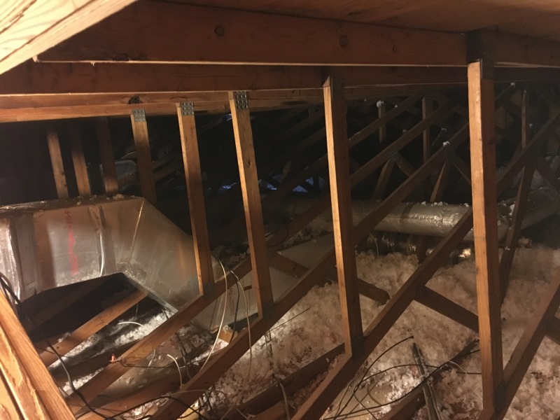
The roof is flat (covered with a single ply TPO membrane over 1/2" iso board, which is over 1/2" plywood sheathing). The trusses are parallel chord type and are spaced 24" OC across the roof and are comprised of 2x4 members. The span between vertical supports is ~12 ft and the depth of the truss (measured between the outside of both the top and bottom chords) is ~68" A photo is below.

IMG_5830_h5qdvk.jpg
.

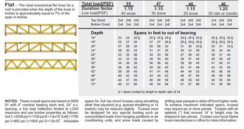
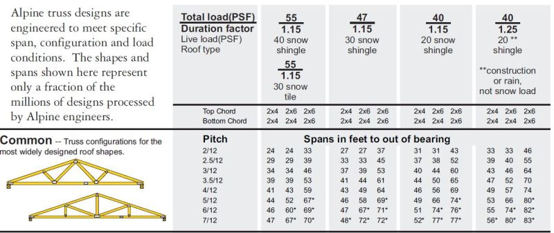
Is there an easy way to determine the maximum load in psf this roof could be expected to support? I'm going for permit for the solar system this is going to be question 1 that I have to answer. Thanks for the help!
 
Replies continue below

Recommended for you

Since they are pre-engineered roof trusses, they won't be designed for any more than the code minimum loads (whether that be the snow load or a 20psf live load). I'd bet my money on the ballasted approach not working due to this fact.
 
jayrod12-

Thank you for the reply. These trusses were installed in 1977....so yes whatever code was then is likely what they were designed for. I am near Tampa, so no snow load.

Is 20 psf the "norm" as far as live load designs?
 
BTW, the solar panels themselves are maybe 3 psf dead load, and from what I have ballparked thus far for ballast (just in looking at other installations in the area which are permitted), I'm wondering if a 20 psf design roof may just prove sufficient.
 
I'm not 100% confident as I practice North of the border, but typically yes a 20psf live load is the norm for roofs that don't have snow. This is to account for the odd person getting up there and walking around.

You'd obviously need a local structural guy to review and sign off, I assume at this point you're just investigating feasibility.

 
Jayrod12-

Yes...right now I am just seeing what may be possible. Before I get too deep into this Id prefer to know if I am in the ballpark or not!

Here is a photo of a "legit" (i.e. permitted) installation of a ballasted system in my town. In looking at the ballast blocks, it doesn't look like a huge amount was required and the spacing may be enough to fall below the ~20 psf (which I know Id still need to confirm). I'm guessing that the ballast in each of the trays is ~50-60 lb. In looking at the area of each panel and the total load in a given area, it seems as though (if this photo is a reasonable guide) that the total load would be less than 20 psf?

ballast_aitfzy.jpg
 
yes, I second getting a local structural engr to check this out not only for the extra imposed dead load but also for the whole idea of ballast solar panels in resisting the wind uplift/turbulance on this particular roof which varies according to the particular layout of a given roof....
 
Agree with SAIL3 - get an engineer to help you. And technically you can't "steal" roof live load capacity from the roof for added stuff on the roof unless the added stuff changes the required roof live load (i.e. greenhouse, etc.). You could probably argue that the solar panels would tend to minimize any applied loading from people - but there's also rain loads that the codes require and I doubt those would be reduced by the presence of the solar panels.


Check out Eng-Tips Forum's Policies here:
faq731-376
 
All-

I will def get a local structural for the permit drawings, but before going there (again as a feasibility study), Ive found the below truss load table online.

My trusses are ~30 ft long between bearing points and as mentioned above appear to be parallel chord type and are comprised of 2x4 members. The depth of the truss (measured between the outside of both the top and bottom chords) is ~68"

In looking at this table, and again just ballparking things to see how feasible this is, this truss might be capable of fairly significant load?

Truss_Table3_gixpxb.jpg
 
BufordTJustice:
Your roof framing system is a crazy looking parallel chord truss framing system, if that’s what it is or what you call it. It isn’t like the parallel chord trusses you show. The truss spans about 30', the trusses are spaced 2' o/c, but the top chord appears to be a 2x4 or 2x6 spanning horiz. 15', from one truss bearing line to the center of the truss (the ridge) and then another 15' on to the other truss bearing line. There are no diag. members supporting the upper chord in the plane of the truss. The real load carrying truss seems to be a 30' long std. gable truss with about a 4/12 pitch (5.67/15). Then there is a 30' top chord fixed to the top of the gable truss, to carry the ½" roof sheathing and roof loads. That won’t support a ballasted solar panel system and it won’t take much of the uplift in your neck-of-the-woods either. 15' is a very long span for a 2x4 or 2x6 with ½" sheathing.
 
dhengr-

Great stuff!

I was actually just looking online for other truss tables that matched more closely with mine. Your note that it really is just a standard/common gable truss with another 2x4 running horizontally 15 ft from the center of the truss out on each side immediately made sense to me. Thank you for this insight.

So as far as the load carry capability of the truss itself (ignoring the funky 15 ft 2x4 spans running horizontally), the below might be a reasonable approximation?

And, do you have any estimations on what the 15 ft 2x4 span can support? I am guessing its going to be less than 20 psf! If so, to correct that can vertical 2x4s be used to transfer that load downward at mid span (i.e. make the span ~7.5 ft rather than ~15 ft)?

CommonTruss_zs3v9o.jpg
 
OK....the truss is actually slightly different than I described above. I believe the base truss, as dhengr notes, is a simple common truss that is ~30 ft long. The additional 15 ft horizontal top "chords" are actually supported with a vertical member at ~11 ft span from the center of the truss as shown in the photo below.

IMG_5835_gibykc.jpg
 
My lord that is an ugly set up now that we see more pictures of it. Those verticals that support the 2x4 framing don't even line up on a truss panel point. Scary proposition.

You need to have someone come out, review and measure the framing, and analyze the structure as built to determine the capacity.
 
jayrod12-

This house was built (and untold thousands like it around here) by a giant builder of the day (Reutenberg/US Homes). They even provided a big heavy brass plaque to the new homeowners upon completion! So, it must have been good. LOL

In seriousness, we can be sure that this met the code requirements of the day considering whom it was built by (and empirically, this house has seen 100+ mph winds more than once without any uplift issues at all), and I also have 12 pool heating solar panels (each is about 50 sq ft and full of water) on another section of the roof and there are no issues with that (they have been through hurricanes as well) so funky as all this is, it was someones good idea at one time and seems to work :)

Unfortunately, the fact that it is non something I can look up in an online table or otherwise reasonably estimate, means it may have overly complicated my solar pursuits :-(
 
I suspect that the average global-distribution weight of the ballast stones would end up much more than the typical 20psf roof live load value. The design wind uplift alone on the surface of the panels (a C&C load) would surely be much in excess of this - especially with a 145mph design wind speed. And I think that you also have to tether these against hurricane displacement - just like you would a typical HVAC rooftop unit, or a sign.
Dave

Thaidavid
 
This is great conversation...thank you to all have replied.

Some further estimations using the above installation photo of the ballasts. As I know this is an acceptable installation that passed all permitting requirements it may be a decent basis for speculation-----

I believe those ballast blocks are ~32 lb each and there are 3 on each ballast tray (for ~96 lb total ballast in each tray). The tray itself is ~4 lb, so we are at ~100 lb total per tray.

In looking at the above solar panel layout, for a given 8 panel section, there are 15 ballasted mounts. So, this means over that section there is ~1500 lb added, plus the panels themselves.

These panels will typically be ~40 lb each and measure ~65"x39" (or ~17 sq ft each).

The panel rows are spaced ~18" apart.

So, the total weight of the 8 panel array----

8 panels x 40 lb each = 320 lb
15 ballast trays x 100 lb each = 1500 lb
1820 lb total

The total area covered-----

2 panels x 39" (3.25') = 6.5 ft length
4 panels x 65" (5.4') = 21.6 ft width
Total panel area = 6.5' x 21.6'= 140.4 ft^2

Adding in the spacing between panels rows where panels do not reside-----
18" (1.5' spacing between rows) x 21.6 ft width = 32.3 ft^2

Total area of the 8 panel array = 140.4ft^2+32.3 ft^2 = 172.7 ft ^2

So, the total added load would appear to be---

1820 lb / 172.7 ft^2 = 10.5 psf.

Does this rationale make sense to you guys? I believe the ballast requirement is surprisingly low due to the relatively flat mounting angle of the panels. They appear to be <10 degrees.


I don't know if the picture of the roof in your town is taken in a high wind area, but if a big hurricane goes through there, I would expect those panels to be scattered all over the county, permitted or not.
 
hokie66-

Yes that building is in a high wind area less than a mile from the coast. It did see a hurricane 2 months ago. It wasnt a cat5 hurricane (maybe cat 2) but if a cat 5 comes through then the last thing well be worried about are solar panels :-(

But, my area does require near cat 5 design conditions for anything new and I have confirmed with the building department that 145 mph is the design they want. So, these panels (which are a fairly new installation) must have had to have met this ~145 mph requirement at least on paper!?!?!?

I really think the low panel angle is what makes this permittable. If these panels were at a 30-40 degree slope, one would suspect the uplift would be much much higher. But, I am not sure on all of this (which is why I am here on this board).
 
You shouldn't consider the area between panels -- even if you successfully argue that the panels prevent people from walking on the area those cover, there's nothing to prevent people from walking between panels (and they likely will, for installation or maintenance).

It's tough to tell from the photo, but I expect that the ballast blocks may also weigh more than 32lb/ea.

----
The name is a long story -- just call me Lo.
 
Does this make sense?

1820 lb total load added to roof over 15 locations = ~121 lbf uplift resistance per mount?

So, if I calculated the uplift imposed on the panel at ~145 mph and it was less than 121 lbf at each mounting location, the panels would be assumed to remain in place?

Part of this seeming to work may also be from the deflector panels which are used. It appears these are used on the high end of each panel mount and dont allow much wind to get under the panels (and therefore limit uplift).
 
Status
Not open for further replies.
Back
Top