Continue to Site

Eng-Tips is the largest engineering community on the Internet

Intelligent Work Forums for Engineering Professionals

  • Congratulations cowski on being selected by the Eng-Tips community for having the most helpful posts in the forums last week. Way to Go!

Diagonal compressive failure of concrete 1

Status
Not open for further replies.

hardbutmild

Structural
Aug 10, 2019
294
Hello,

this is my first post, I usually watch other threads and find most of the answers so thank you for that.

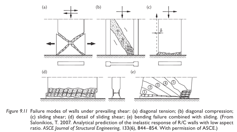
My question is does anyone here know where the expressions for diagonal compressive failure of concrete come from?
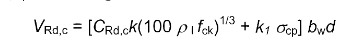
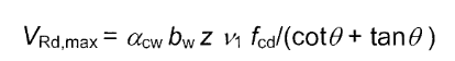
To clarify, I'm talking about the maximum shear resistance that an element can have before the diagonal strut fails under compression, in eurocode it's denoted as VRd,max.
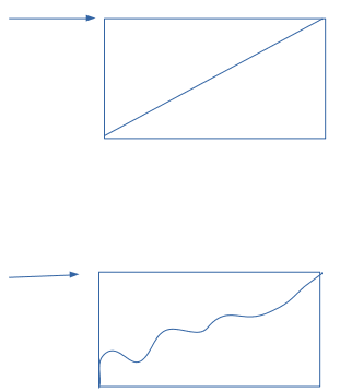
Now, I do know how to get the expression from some basic statics and geometry, but I want to check how the actual experiments to confirm it were done. I want to do this because I think that the expression is valid only for elements with low ductility. Here is my reasoning behind it. In the standard procedure you basically check the strut for failure and it should be the same at any point on the strut, but at the point where the strut connects with the compression area (caused by bending) a 2D stress field occurs. In other words, if bending causes large stresses in compression area, at that point less diagonal stresses can be transferred (basically I check main stresses and not just normal and shear independently).

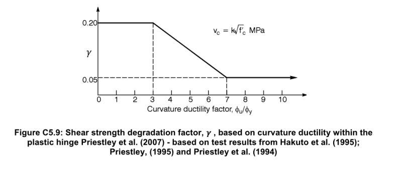
Why do I care for all this? Well, because of walls in earthquake. Eurocode 8 states that you should reduce this strength to 40% (that's 2,5 times reduction!) of it's basic value for high ductility class DCH (EN 1998-1 section 5.5.3.4.2 if you want to check), but no reduction for medium ductility. Further they say that this is "due to dynamic nature of the loading", but the dynamic nature is present in both ductility classes and usually tests are made by static pushing of the wall so it makes more sense that it's due to ductility.
I'm trying to figure out what really happens because this reduction is HUGE, this strength can not be increased by adding reinforcement and shear failure is non-ductile and should be avoided at all cost. It just feels very important.

I'm sorry if this is not coherent, too long or if I posted it in the wrong place. I can provide way more explanations if needed but I didn't want to put too much in the first post.
If you can give any insight into anything related to this I'd be very grateful, thank you!
 
Replies continue below

Recommended for you

@klitor
I thought it'd be a lot quicker to just ask if someone knows how the original VRd,max was acquired because the expression given in the picture you provided has a lot of "problems". First of all, ductility stops influencing the strength at a low value (between DCM and DCH lowest DCH value). It makes no sense. Also, reinforcement shouldn't influence the VRd,max at all so what's that all about? Also, reinforcement has no upper value! So if you put a huge amount of reinforcement you could avoid crushing?

I know it's a fitted expression, but it's not even dimensionally correct and mechanisms are kind of unclear.

I've looked at that article they say is the source but it is very confusing, it seems like they used only a few walls of ductility above 5 and a lot of tests were done by an equivalent static method.

I was just curious if someone saw an article explaining mechanisms that cause this reduction or if someone knows how tests are done for the original VRd,max. Because according to the picture you attached this is also true for ductility 1 (or 0 as they say). They also don't mention if this is dependent on the rate of loading (I'd expect that if it's because of dynamic nature). Because if original VRd,max was done only for plastic ductility 0 then maybe the same thing would happen for non-seismic structures when they behave non-linear.

It's also very weird because I'd expect that it depends not only on the current ductility, but also the total ductility capacity.
 
“we didn't want to put any reductions for medium ductility so that wall systems could be economical"

Isn’t this your answer then?
 
Not economical if you have to replace or repair after each shake though.

Slightly more economical to build in the first place, but if the first decent shake damages it beyond repair, isn't that false economy?

Then you have to ask is it really economical if you consider you might be paying for it twice when you roll the dice on whether you'll see the big one within the life of the building.

Most of the ductile concrete structures in the NZ 2011 earthquakes functioned well in terms of life safety (except the two that collapsed with a good proportion of the 165 odd dead inside them), however most have been knocked down now because of the economics of repair (not entirely structure based, often the fitout/facade damage meant they are not recoverable from an economic standpoint as I understand it). A lot of the new structures going up favour structural steel out of interest. I'd put some money on it that if we give it some time and some corporate amnesia that we'll be building the same concrete structures in a few decades ready for the next big one!
 
@agent666
I totally agree about the economy part and that's what makes me kind of mad. What's even worse, people don't follow the code even where it's clear what's correct (capacity design is often ignored completely). As you said, everyone seems to forget about earthquakes in a decade or so.

I got a glimpse of a new draft to the code and they seem to be going in a direction of not taking this reduction even for high ductility structures.

@Tomfh
Well, I was hoping for something that explains the mechanisms that cause the reduction of the strength to better understand it.

For example, if you ask why does shear force increase, there's a logical explanation that it's because energy is usually dissipated by bending in the first mode, but not in higher modes so influence of the higher modes on the shear force should not be reduced.
This example has nothing to do with resistance, but I just wanted to show an example how there's a certain logic to it, you can understand why is it happening.
I don't like provisions that just say "oh, reduce this 2,5 times because I said so", especially if it's because of a certain phenomena and not a safety thing. Because there is a logic behind it, it can be explained.
 
There is a known degradation in shear capacity with increasing curvature, it's not something someone made up for no reason, i.e. something like this:-

Capture2_c5q8g1.png


This reduction is the outcome of many of the contributing factors noted in discussions above with respect to shear capacity at higher ductility/curvatures in plastic regions.

EDIT- added this as it explains it in words:-

Capture2_g6zlzg.png


The text they refer to is this one:-
Displacement Based Seismic Design of Structures by M.J.N. Priestley
 
@agent666
Yeah, i know it's not made up for no reason. Thank you for a suggestion on reading material. I've already seen this book many times, but was never able to get it.

The graph kind of makes me sceptical, this expression is used for determination of shear strength if failure is due to tension. I think I read one of the articles mentioned in the text and it was tensioned based failure. I attached a picture to show what I mean by tension or compression failure.

shear_failure_oaxewd.png


I seem to mention this a lot, but tension controlled failure means nothing because in design you consider Vc = 0. You don't however consider Vc,max = 0 (or VRd,max or Vu,max). You can't influence Vmax by adding any type of reinforcement, just by changing the thickness of a wall.

Since those are different mechanisms, their degradation shouldn't be the same. For example, due to dynamic nature the cracks smooth so mechanical interlock becomes weaker. While that may be important for tension controlled failure it doesn't make any difference when talking about compression controlled failure.

I'm sorry if I don't make much sense, I don't know, maybe I think there is something that doesn't exist.
 
I think you are possibly confusing concrete cracks (principle tension issue at crack location) with zero or limiting shear strength occurring due to crack forming. To be honest I'm having a few issues following your argument, however I'll point out again that its been explained a few times that this isn't the primary mechanism related to shear strength in concrete, its aggregate interlock in relatively simple terms, the bits between the cracks can still carry load more dependably. You keep coming back to the tension argument on a macro level being a driver to explain the behaviour, but it seems flawed to me (at least) as its one part of a number of complex concrete mechanisms that are no doubt going on.

You posted a number of failure mechanisms related to shear, most standards design rules probably cover these mechanisms. They just aren't exposed to the user. Our code has specific rules for preventing sliding shear (which only governs at very high shear demand). All this does is make sure you have more shear reinforcing, the contribution from the concrete is still the same. But one function of the addition of the reinforcement ensures also that you can develop this concrete component in a dependable manner.

A member could be cracked to hell and still have shear strength. That curve I posted is a result of many mechanisms, I don't think you can boil it down to a single factor which you might be searching for?
 
I think you are in fact wrong. I'm sorry, I just don't know how to better explain it. It's different mechanism altogether. Imagine a flexural failure. A beam can fail in flexure either by tension reinforcement yielding or by concrete crushing. Those are the two possibilities and two different things completely separate from each other. It's the same thing here.

agent666 said:
You keep coming back to the tension argument on a macro level being a driver to explain the behaviour
i don't know what you're talking about. just look at the end of my post, I don't know how to explain it to you. You obviously don't understand that there are compression and tension controlled failures and I posted a pic. I simply can't understand, how does someone not see it, it's right on the pic for god's sake. I can't even argue anymore, it's like we're speaking in different languages.

agent666 said:
All this does is make sure you have more shear reinforcing, the contribution from the concrete is still the same.
HOW? How can you even claim that? HOW? Do you not see the picture? Sliding occurs along a HORIZONTAL crack and tension controlled along a diagonal line. If "concrete contribution" was the same that would mean that if you had no reinforcement whatsoever that tension controlled failure and sliding would occur at the same exact moment. Because their strength is the same. For god's sake, "more shear reinforcing"????? Sliding reinforcement is either VERTICAL or diagonal, shear reinforcement is HORIZONTAL. I don't know... i just give up.

It's simple. Imagine you have a concrete wall. You also have a shear force. You increase this force from 0 to infinity.

At one point due to tension you will get a crack. If you don't have reinforcement it will fail (that's the strength defined by tension).
So you put enough reinforcement to avoid that, but the force keeps getting larger. At one point concrete crushes!!!!! No amount of reinforcement is going to save you from that! No sir, not possible to avoid by adding steel.

Now what does this tell us? That since tension and compression failure aren't simultaneous they must be caused by different mechanisms.

As a matter of fact, here is an article (I found it on the site of a uni so I guess it's openly available)
Look at the chapter 4. You can see that there are different expressions for shear in tension and compression and their strength reduces differently.


In fact, look at this formulas taken from eurocode, this one is for tension controlled shear failure
tension_qrwpft.png

k takes into account size effect, ro is the influence of longitudinal reinforcement, sigma is the influence of axial load

Now look at the expression given for compression controlled failure
compression_z6rcdh.png

alpha is the influence of axial force (okay, same or similar mechanism as in tension)
ni is the influence of cracking
theta is the influence of strut inclination (doesn't exist in tension failure)
where is the influence of longitudinal steel???
This expression shown in the second picture can easily be derived from simple statics and geometry, just see when you get compressive strength on a diagonal because of shear force.
The first expression on the other hand usually can be described by 3 different mechanisms
1) part of the section in compression due to bending resists some shear due to friction basically and since it's compressed that helps
2) mechanical interlock along the crack
3) dowel action of tension reinforcement

Influence of each one of them depends on things such as size of the element (remember, it seems to not be important for compression controlled failure) and also on the amount of reinforcement (find me where's the reinforcement in the second formula please)

I can't believe we even have to discuss the fact that compression controlled and tension controlled failure rely on different mechanisms and that their reduction is MOST CERTAINLY different.

agent666 said:
That curve I posted is a result of many mechanisms, I don't think you can boil it down to a single factor which you might be searching for?
I'm not looking for one factor, but for the love of god man... it's NOT THE SAME MECHANISMS! you not seeing that is simply unbelievable to me. It's absurd. We're discussing something that is clearly different. Why would different failures even exist if all of them depended on the same mechanisms? They can have some mechanisms in common, but OBVIOUSLY not all. You want proof? well look at the reduction suggested by priestley and the one I said from a paper by biskinis and fardis and a few others. They are different. I just can't anymore... I simply can't. It seems trivial to me that different modes of failure are in fact different.
 
Dude calm down alright, I'm trying to help contribute to your random question on the internet. I'm not getting anything out of it at all. It seems that whatever reasonable explanation people have had in this thread isn't for you, you don't believe or want to rely on well recognised texts, phenomena, etc. There is zero point coming here and asking a question and then berating everyone that tries to help because you don't believe part of what they have to say.

Yes there are all different types of shear failure. I recognise that, never disputed it. For practical design, who really cares, codes evaluate a lower bound solution that you hope precludes all different types of failures. Can you say for certain for a given configuration what type of failure will occur knowing how variable concrete and reinforcement factors can be.

As to which limit state ultimately governs depends on the load compared with the capacity for that limit state, inclusive of concrete and/or shear reinforcement capacities, etc.

Sliding shear for example occurs at higher levels of shear in reversing plastic regions, to prevent sliding shear you need more shear reinforcement as I noted (at least this is how the NZ standard treats it, sometimes diagonal reinforcement or inclined bars are required above certain limits of shear stress because as per the graphic you posted traditional orthogonal reinforcement doesn't cross the shear failure plane).

This additional reinforcement does not create more 'concrete capacity'. The amount derived from the concrete component is constant irrespective of the mechanism of shear failure (the first equation in your post above for Vrd,c). Your standard may have different means of treating/checking these types of failure mechanism. NZ standard covers 'sliding shear' and 'standard shear' and your 'compression shear limit' as an upper bound on shear strength.

In the NZ standard the maximum shear limit is a function of concrete strength or a constant stress (I think 0.2f'c or 8MPa from memory, though the later changes depending on the type of component, beams/walls/beam-column joints all have varying max shear limits), it is simply an upper limit cutoff to be compared to concrete + reinforcement shear capacity. If your traditional shear capacity calc is higher than this limit, then that limit governs the capacity instead, if your load is less than this you are good to go. YThere is no means of enhancing the strength beyond this limit except increasing the concrete strength or wall geometry, and even then you run into the 8MPa limit at some point. In practical design the compression limit Vrd,max would very rarely be the limiting factor, obviously if this is an upper limit, and in ductile design the Vrd,c was reduced to zero then there is no way the other Vrd,max limit even comes into it even if there is a different reduction applicable. I agree there may well be a different rate of reduction, but my guess is the reduction is a lower bound, applied equally irrespective of the final limit state at which the member might fail (see last few paras below).

In Eurocode it works exactly the same way as far as I can tell for conventionally reinforced members, I'm only stating this so I know we are all on the same page here...
Vrd is the lesser of
Vrd = Vrd,max
or
Vrd = Vrd,s + Vrd,c

So the point I want to make is the V,rd,max limit is compared to the strength of the sum of the reinforcement + concrete strengths, it's not a limit on just the concrete shear strength in case there was any misunderstanding on this, to achieve that capacity it is reliant on there being some minimum level of reinforcement present. This is identical to how the NZ standard is laid out. I don't think I said it had anything to do with increasing if we added more reinforcement, as noted above I was referring to the sliding shear limit state when I stated this (sorry if this was unclear).

The curve I posted isn't a function of the many types of individual failure limit states being reached, its a function of what mechanisms are going on inside the concrete at a given yield curvature ratio such as degree of cracking, degree of concrete crushing, degree of aggregate interlock, degree of reinforcement elongation, other factors you've noted, etc as it affects the shear capacity derived from the concrete contribution. These mechanism applies equally to the concrete shear capacity (your first equation for Vrd,c above). The 'material' mechanisms I referred to are these, not the individual ultimate mechanisms of failure to clear up your point about not being the SAME MECHANISMS.

They are different modes of failure, and they may well have different rates of decay, but the same 'stuff' is going on inside the concrete up until any one of these failure mechanisms is reached if you like and I guess that the codes take the most conservative value in developing the degradation curve, a lower bound value that may not recognise the actual capacity if a given configuration happened to fail in another manner. Does it always reflect reality, maybe not, but does it make the economy of design easier for the poor designer not having to evaluate 6 different failure states by knowing that you only need to evaluate the most critical code approach, hell yes. In a cyclic hinge, concrete is getting hammered in reversing compression/tension/shear, so arguably at that point a universal reduction is palatable because all those mechanisms are occuring in the same bit of concrete in a full cycle.

Have you plotted out those degradation curves from the paper so you can share the differences? I guess in terms of what you design for only if they crossed and one was more critical at certain levels of load than the other would it be of any practical use.


The code rule being refered to only reduces VR,max. So is that saying if you are well below VR,max that shear degradation need not be considered?
 
Well, depends on how "well" bellow the VRd,max you actually are. If you're bellow 0,4 VRd,max then technically yes, but ONLY because you already say Vc = 0. Since the code says that no contribution of concrete should be considered when determining tension controlled failure they didn't introduce any reduction for that, but it obviously should exist and should be different than the reduction of VRd,max.

So according to the code, if you have no reinforcement, tension controlled failure occurs at V = 0 and compression controlled occurs at V = 0,4 VRd,max.

If you add some reinforcement, tension controlled failure changes, but compression controlled doesn't.
 
agent666 said:
you don't believe or want to rely on well recognised texts, phenomena, etc.

I do recognise them and accept them. They just address the question of tension controlled failure and not the one I'm talking about. It's as if I ask about a chicken raising manual and you give me a duck raising manual. Close enough.

agent666 said:
The amount derived from the concrete component is constant irrespective of the mechanism of shear failure (the first equation in your post above for Vrd,c).

It isn't, but I don't have the energy to discuss this anymore.

agent666 said:
If your traditional shear capacity calc is higher than this limit, then that limit governs the capacity instead, if your load is less than this you are good to go.

exactly, and I'm talking about the reduction of this limit, not the reduction of Vc. and it's not "just an upper limit".

agent666 said:
In practical design the compression limit Vrd,max would very rarely be the limiting factor, obviously if this is an upper limit, and in ductile design the Vrd,c was reduced to zero then there is no way the other Vrd,max limit even comes into it even if there is a different reduction applicable.
It does, I've seen it happen a fair amount of time in practice since it's reduced to just 40% of the standard value. Especially for walls with smaller thickness when you consider that concrete cover spalls.

agent666 said:
I agree there may well be a different rate of reduction, but my guess is the reduction is a lower bound, applied equally irrespective of the final limit state at which the member might fail (see last few paras below).
As I pointed out a number of times it's a lower limit for DCH, butnot for DCM (DCM is mostly used in practice).

agent666 said:
Have you plotted out those degradation curves from the paper so you can share the differences? I guess in terms of what you design for only if they crossed and one was more critical at certain levels of load than the other would it be of any practical use.
They most certainly cross. Because as you said V = Vc + Vs and Vrd,max are in question.

So when you have a large enough amount of steel V will be larger than Vrd,max and I saw examples in practice and had a few people call me about it.
It's so obvious. We even talked about it in this thread. There's a picture of a guy who wrote the code saying "we didn't put it in because it would limit the usage of this system". That's the proof that it would have influence.

All I tried to say by "different mechanisms" is the following. Consider the picture
failure_ho5bai.png

both of these can fail either by one triangle sliding on the other along a line or curve.
Another failure can occur by crushing of the diagonal.
Now, both of these will crush at the same force, but won't slide at the same force. That's all I meant, that some things that are important for one type of failure aren't important for other type. So if you say that reduction of sliding capacity occurs because the bottom pic became top pic, crushing won't care because it's independent of the roughness of the crack. So one of them can decrease without the other one decreasing.
 
Status
Not open for further replies.

Part and Inventory Search

Sponsor