EngDM
Structural
- Aug 10, 2021
- 744
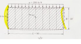
Does anyone have a resource of a design example for a roof with diagonal decking installed at a 45°? CSA O86 doesn't provide much of anything aside from some commentary on it, and the only diagram they give is for a shearwall.
O86 instructs me to design the boundary members (chords) for the out of plane component, but since the decking members don't have shear transfer between adjacent members I can't quite figure out my load path to determine the loads on these members. O86 gives an equation, but it appears that it is assuming that the chords are one continuous member from one shear collector to the next, whereas I have edge purlins that start and stop. That is to say, the bending moment diagram of the decking would be based on the overall length between collectors, but each individual edge purlin is 1/4 of that length since I have 4 bays.
Similar to the above, I can't see how without shear transfer between the planks, that load in the N-S direction actually makes it out to the shearwalls on the left and right for the option 1 framing. If I draw the UDL and try to follow the load path, it almost seems that the left wall never has any load dragged into it. Is the assumption that the load goes axially into the plank, then at purlin intermediate supports it jumps over and makes it way out?
My shearwall orientation is 2 endwalls and a central wall, so a large H shape essentially, but for wind in the direction parallel to the single central shearwall the load path doesn't appear to actually make it to the center unless I change the decking orientation at some point to start collecting it into the middle.
I've attached a crude sketch of the framing, intended shearwalls are currently shown red. The north and south walls are full of openings and can't be relied on as shearwalls (I haven't drawn the openings). Planks are drawn for orientation only, not drawn to scale.
Attachments
Last edited:


