Eng-Tips is the largest engineering community on the Internet

Intelligent Work Forums for Engineering Professionals

  • Congratulations waross on being selected by the Eng-Tips community for having the most helpful posts in the forums last week. Way to Go!

Diagonal reinforcement - hammer head bridge

Status
Not open for further replies.

Nayan67

Civil/Environmental
Feb 8, 2023
28
PH
Hello everyone,
I was just curious about the reinforcement detailing in the hammerhead beam. Is there any particular reason for using diagonal reinforcement (please see the attached figure)?
Regards
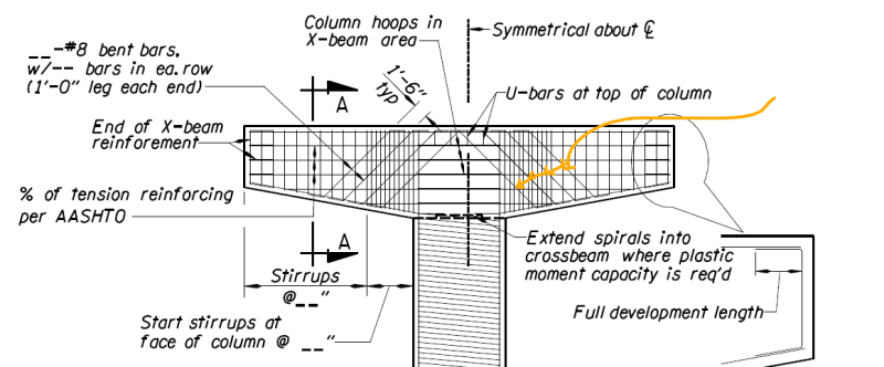
Diagonal_rebar_-_hammerhead_rucjzs.png
 
Replies continue below

Recommended for you

Sure does present like vintage shear reinforcement. Why that's desirable in this situation isn't clear to me.
 
KootK,
Thank you for the response. Actually, we were in the process of detailing the beam when we came across this recommendation provided by Oregon DOT. We couldn't find a specific reason for the diagonal reinforcement and have no idea why it's needed. That's why I'm reaching out here, hoping to gain insights from practicing engineers.
Regards
 
Properly proportioned, those bars would be quite good at limiting the size of shear cracks though that area.
 
KootK said:
Properly proportioned, those bars would be quite good at limiting the size of shear cracks though that area.

Would shear friction and monolithic surface properties be the proper means to proportion this?

How does that strength interact with the traditional shear reinforcement? There are a lot of stirrups already... I'm curious how many legs there are in each stirrup line.


dL said:
Would shear friction and monolithic surface properties be the proper means to proportion this?

I'm not sure really. I've never designed crack control reinforcement for shear cracks. I was just spit balling some alternate explanations for those diagonals other than just overflow shear capacity. That said, if it were crack control, I think that would be about separation at the joint rather than relative slip across it and, therefore, probably not shear friction.

 
I thought we stopped doing bent bars in the 70's. In the old AASHO, it's shear reinforcement, or as they called it, web reinforcement. AASHO allowed three types: rectangular stirrups, bent bars, or a combination of both.

To me bent bars a detailing headache, although, visually, they convey strength. Prior to the 1977 AASHTO, the allowable shear strength in previous versions of the code was much higher. Maybe those diagonal bars actually help in some strange way.
 
I like bars that cross the shear plane orthogonally, as those would. But #8 bars with only a 12" leg each end might not be very effective. The other concern is that most of the shear reinforcement is in the area close to the support, and not much out near the shallow end.
 
I like bars that cross the shear plane orthogonally, as those would. But #8 bars with only a 12" leg each end might not be very effective.
They're developed where they need to be - at the location of the potential shear cracks. The 1' bent leg on the end is primarily to make it possible to tie the bars to the other steel.

The other concern is that most of the shear reinforcement is in the area close to the support, and not much out near the shallow end.

It depends on where the girders bear on the cap. Presumably, the closely-spaced stirrups would extend to where the first interior girder bears. Beyond that, the shear demand is reduced to half or less than half of what it is from the second girder to the face of the pier shaft.
 
Status
Not open for further replies.

Part and Inventory Search

Sponsor

Back
Top