Continue to Site

Eng-Tips is the largest engineering community on the Internet

Intelligent Work Forums for Engineering Professionals

  • Congratulations SDETERS on being selected by the Eng-Tips community for having the most helpful posts in the forums last week. Way to Go!

Diagonal sawn lumber as roof diaphragm 2

EngDM

Structural
Aug 10, 2021
646
Does anyone have a resource of a design example for a roof with diagonal decking installed at a 45°? CSA O86 doesn't provide much of anything aside from some commentary on it, and the only diagram they give is for a shearwall.

O86 instructs me to design the boundary members (chords) for the out of plane component, but since the decking members don't have shear transfer between adjacent members I can't quite figure out my load path to determine the loads on these members. O86 gives an equation, but it appears that it is assuming that the chords are one continuous member from one shear collector to the next, whereas I have edge purlins that start and stop. That is to say, the bending moment diagram of the decking would be based on the overall length between collectors, but each individual edge purlin is 1/4 of that length since I have 4 bays.

Similar to the above, I can't see how without shear transfer between the planks, that load in the N-S direction actually makes it out to the shearwalls on the left and right for the option 1 framing. If I draw the UDL and try to follow the load path, it almost seems that the left wall never has any load dragged into it. Is the assumption that the load goes axially into the plank, then at purlin intermediate supports it jumps over and makes it way out?

My shearwall orientation is 2 endwalls and a central wall, so a large H shape essentially, but for wind in the direction parallel to the single central shearwall the load path doesn't appear to actually make it to the center unless I change the decking orientation at some point to start collecting it into the middle.

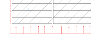
I've attached a crude sketch of the framing, intended shearwalls are currently shown red. The north and south walls are full of openings and can't be relied on as shearwalls (I haven't drawn the openings). Planks are drawn for orientation only, not drawn to scale.
 

Attachments

  • Decking Layout.pdf
    10.6 KB · Views: 10
Last edited:
Replies continue below

Recommended for you

This has mostly gone away in the US — every state-adopted code that I’m aware of requires solid decking, and planks don’t qualify. When you say diagonal, I think decking planks, per your sketch. (I see this in floors—usually in older buildings—but never roofs, so far).
 
This has mostly gone away in the US — every state-adopted code that I’m aware of requires solid decking, and planks don’t qualify. When you say diagonal, I think decking planks, per your sketch. (I see this in floors—usually in older buildings—but never roofs, so far).
CSA O86 has a table and describes it; as far as I am aware it is not prohibited. The planks are pieces of 2x6 T&G, and is a specific request from the client. I would personally rather sheet the roof and have the T&G as decorative only (maybe rely on it as the backing for the sheething) since the purlin spacing is 5' and doesn't make for nice transitions with 4'x8' sheets.

I have seen this in older wood framed buildings, but from mid-late 1900's.
 
My answer requires some qualifying nuance, which will actually be helpful to you. Not all roof coverings require “solid” decking, which I believe is defined by roofing manufacturers with respect to maximum spacings and such. It’s just getting rarer to come across a cedar roof these days.

Anyway, it begged the question of how those diaphragms were designed, as I’d never done it. To wit, I checked the 2021 SDPWS, and there are provisions for diagonal lumber. Refer to 4.2.8.2. Sorry for burying the lead there.
Is there a way to get the SDPWS viewer to not be so blurry? I don't have a copy myself since it's not a governing code here.

Edit: I've read the section you mention, and it is pretty similar to what O86 says. I just don't quite understand how the load goes from the windward/leeward faces out to the shear collectors without the 2x6's being fastened to eachother somehow. Like if you take a vector as shown, how does the load ever make it out, especially for planks crossing multiple bays.

vector.png
 
Last edited:
Is there a way to get the SDPWS viewer to not be so blurry?
I have the same gripe, so I bought a soft copy. Copyright prevents me from sharing it, unfortunately. Looks like Scribd has it as the third hit on Google; I don’t know how reliable that website is. What a weird time in history to be an SE.
 
I've designed many repairs and additions to diagonal sheathed roofs. I use the allowables from the SDPWS as I practice in California and design it like any other flexible diaphragm. You will need to provide a typical detail showing how the joints are staggered, ie. the adjacent diagonal boards joint does not line up with the boards next to it.
 
how does the load ever make it out
Mostly friction. Tested assemblies were about twice as stiff as real roofs that dried/shrunk in service, so the calculated deflections (in the tables) account for the additional flexibility. Some nail slip is also anticipated, so even planks that have shrunk away from each other eventually mobilize enough friction through deformation and nail slip.
 
I just don't quite understand how the load goes from the windward/leeward faces out to the shear collectors without the 2x6's being fastened to eachother somehow.

Each deck board to joist connection has at least two fasteners. Those function as a bunch of little, highly questionable moment connections. So it's kind of like a Vierendeel truss of sorts.

With respect to the calculation of boundary element forces, this changes nothing relative to a conventional diaphragm. The mechanism of shear resistance is just different. And worse obviously.

It's not as though deck boards are the only funky diaphragms out there. Corrugated steel deck does a pretty nifty, in plane, torsional mambo under shear strain.
 
Functionally, it's not much different from an unblocked plywood sheathed diaphragm. It's not as if all those sheets of plywood are attached together either, APA recommends a 1/8" gap between sheets.
 
Each deck board to joist connection has at least two fasteners. Those function as a bunch of little, highly questionable moment connections. So it's kind of like a Vierendeel truss of sorts.

With respect to the calculation of boundary element forces, this changes nothing relative to a conventional diaphragm. The mechanism of shear resistance is just different. And worse obviously.

It's not as though deck boards are the only funky diaphragms out there. Corrugated steel deck does a pretty nifty, in plane, torsional mambo under shear strain.
So the diaphragm moment is still calculated as we normally do, and we get the chord forces by dividing by depth as normal, the only change is that the chords get designed for an our of plate element as well as axial.

Is there any inherent issue with the singular central wall that would be present with using T&G decking vs a typical blocked diaphragm?
 
Functionally, it's not much different from an unblocked plywood sheathed diaphragm. It's not as if all those sheets of plywood are attached together either, APA recommends a 1/8" gap between sheets.

Exactly. Were it not for cringe worthy, lab tested shear resistance mechanisms, where would we be? Australia??
 
Is there any inherent issue with the singular central wall that would be present with using T&G decking vs a typical blocked diaphragm?

Nothing is jumping out at me.

the only change is that the chords get designed for an our of plate element as well as axial.

I'm not familiar with this. In this context, is "out of plane" vertical or horizontal? Can you post the relevant clause?
 
Nothing is jumping out at me.


I'm not familiar with this. In this context, is "out of plane" vertical or horizontal? Can you post the relevant clause?
So out of plane would be a lateral load in this case. In plane loading is typically gravity loading, or loading that is parallel to strong axis. I don't have my O86 on me at the moment, but IIRC 11.6.5 addresses effects on boundary elements.
 
So out of plane would be a lateral load in this case.

Not sure I agree. In the context of diaphragms "out of plane" usually means perpendicular to the diaphragm, so vertical. That said, I've not checked O86 myself.

If you're to design the boundary members for loads about their own weak axes, what loads then? If it's the lateral load on the diaphragm, what's the point of the diaphragm? Me no underando.

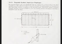
4.2.8.3 of 2021 SDPWS2021 says:

"Each chord shall be considered as a beam with uniform
load per foot equal to 50% of the unit shear due to dia-
phragm action. The load shall be assumed as acting nor-
mal to the chord in the plane of the diaphragm in either
direction."

The O86 commentary reads:

"Loading on single-layer shearwalls and diaphragms creates additional forces that need to be addressed in design. These forces occur in the boundary members parallel to the interior framing members (i.e. studs in shearwalls or joists in diaphragms). The normal load component, acting perpendicular to the boundary member, creates a moment, Mf, that must be accounted for in the design of the boundary member."

I think this is due to the fact that the planks are installed on 45° angles, so it creates an Fy and Fx component in the decking that needs to get resolved at each end. With typical sheathing I'd wager you are much more rigid such that there isn't really bending of the individual chords.
 
Last edited:
Fascinating. I'll need to withdraw all of my contributions here as it's clear that I don't understand the system on a mechanistic level. I'm getting the sense that this setup is treated as some kind of non-concentric truss but I've not yet reconciled myself to it.
 
Fascinating. I'll need to withdraw all of my contributions here as it's clear that I don't understand the system on a mechanistic level. I'm getting the sense that this setup is treated as some kind of non-concentric truss but I've not yet reconciled myself to it.
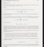
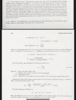
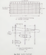
With my limited understanding I think in the 45 degree layup it acts more truss like while straight layup does exhibit the small moment connections you noted before. I think you have the Building Structural Design Handbook while not an extensive coverage it's more than I have seen anywhere else starts on page 966.

1743514484322.png
 

Part and Inventory Search

Sponsor