Have a tight tolerance I need to hold on the ID and OD of a part, but it's only over a 1/2" section. What's the cleanest and most proper way to notate this?
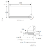
Ok so if I go ahead and use a chain line, how can I best specify the rest of the diameter to have a looser tolerance? Just show that in another view? Attached is what I currently have (I've increased my limited length to 0.875):
Ok so if I go ahead and use a chain line, how can I best specify the rest of the diameter to have a looser tolerance? Just show that in another view? Attached is what I currently have (I've increased my limited length to 0.875):
It's useful to mention what sort of blend is allowable between the two areas. It is also not necessary or valuable to use a basic dimension as there isn't any control on the variation in the controlled length. It's probably useful to include a cylindricity geometric characteristic control with a small variation or to specify AVG DIA to allow for flex.
It would really help the manufacturing if there was a shallow round-bottom groove to separate the two areas so that whoever sets up to make the smaller variation area doesn't have to worry about gouging into the larger variation area and vice-versa.
It is my opinion . Basic dimensions are over used. It will only irritate the shop.
Think about the geometry, size matters.
What tooling is required what machinery is required. How is this part manufactured.
Yet satisfy the design intent.
This part is 36.168 mm
And requires very small tools generally on a larger part with adequate clearance a boring bar
With a standard insert of the cutting would be .015 or .025 radius. So a radius of .015-.040
To help minimize stress point.
Think of the difference in diameter.
That is a tiny step.. (.106 mm) and is more difficult to measure. A dental cast is required.
But in this case I would prefer to hone the part straight. The issue is clearance for the mating
Component. As a designer not to have inter ference.
So if pull make the remainder of the diameter
36.188 +/_ .17 as long as the above is satisfied.
Now to make it clear, a foot note
As such, reminder of diameter as noted.
This it minimize machining difficulty. And inspection. And can reduce cost of machining and inspection yet satisfy intent.
On more complex parts and larger the drawing
Would be adequate.
Limited length or area dimensions are a lot like datum target area dimensions. You don't control their variation on the part drawing that uses them, but that's also why you should specify them as basic ("theoretically exact") - you assume that they are exact and someone's job is to make sure that their practical application is accurate enough.
Limited length or area dimensions are a lot like datum target area dimensions. You don't control their variation on the part drawing that uses them, but that's also why you should specify them as basic ("theoretically exact") - you assume that they are exact and someone's job is to make sure that their practical application is accurate enough.
View attachment 7406For dimensions to holes it works perfect , and is a great way of dimensioning. No argument there, and concurr. Buy dimensioning diameter I feel is over kill.
The above example if the mating part lays within that basic dimension it is functional. But guaranty the entire surface will be flat. And to
perp the part both sides will machined flat and parallel. Its called squaring a block.
A machinist can place in a mag plate machine one side then flip it and machine it flat parallel.
Then flip skim cut to remove errors.
In this application as depicted works well.
With a basic dimension on a diameter now the machinist has to calculate diameter based fcf.
Now there is a possibility of accidently writing it wrong. And machining it wrong.
With a diameter with a tolerance not basic he or she knows what size to set the boring bar.
Yes sometimes it may not be exact to ASME.
But company's are allowed to use internal procedures. Even if it not exact to ASME.
If it prevents discrepancy.
mfgenggear,
Yes, I'm not sure why there is the basic dia. 39, maybe OP was thinking to control it with a general profile? Anyway I'd simply specify a larger direct tolerance as in my above suggestion in post #7 (+/-.xxx where .xxx is just loose enough to still not cause any trouble).
Appreciate all of your feedback. I agree that the 39 dia as well as the 36.4 dia shouldn't be basic.. their size really doesn't matter for my application. The only critical part is that shown in Detail D. The Chain line controlling the major dia can also have a pretty loose tolerance by intent to lax requirements on the major dia.
I'm going to be working directly with the machinist who will produce this part, so I'll take his feedback on how to dimension this better given my application.