Eng-Tips is the largest engineering community on the Internet

Intelligent Work Forums for Engineering Professionals

Diaphragm behavior w/ Moment, Braced Frames in same direction

Status
Not open for further replies.

Samwise Gamgee

Structural
Oct 7, 2021
113
0
0
US

I'd like to get some input on the diaphragm behavior with moment and braced frames in the same direction. The main building (300x60) has 7 moment frames and is about 29' feet tall. There is a tower roof area(20x20) which is 40' tall and uses Braced frames. As the tower roof area is tall, moment frames were not feasible.

ASCE says un-topped metal deck is flexible if lateral system is braced frames (the alternative being, with moment frames, we can't consider it to be flexible).

As I have combined lateral systems in the same direction and an un-topped deck, is it safe to consider the diaphragm to behave as flexible ? If I consider it to be semi-rigid all of the load is dragged into the braced frames. My intuition is that due to the combined systems, the diaphragm will behavior somewhere between a flexible and a semi rigid. I talked to a few engineers and they mentioned that its safe to consider it to be a flexible diaphragm
 
Replies continue below

Recommended for you

There isn't really an in between for semi rigid and flexible, semi rigid is the in between. Does the bracing on the roof tower run to grade or sit on moment frames?
 
It would be useful to share a plan view of the structure here.

The braced tower will be like a rigid tree stump sticking out of your, other wise flexible low roof. Any framing lines on or beside the tower are likely to dominated by the stiffness of the tower. Framing lines further afield may start respond according to a flexible diaphragm assumption.
 
KootK said:
So would the standard of care to be consider it as flexible but design the tower roof braces frame for overlapping tributary areas from its adjacent moment frames (maybe 1 bay on either side). Plan is attached below. Solid blue indicates braced frames, light blue are collectors. Solid red indicates moment frames. I am concerned about the wind in Y direction

Capture_tpvlqv.jpg
 
KootK said:
Thanks a ton, the braced framed foundations are designed for 70% of the overall wind in that direction which is conservative. Why does ASCE say I cannot idealize is as a flexible diaphragm per the snip below. The problem with me idealizing it as a semi-rigid everywhere makes the braced frames in the other direction resolve torsion and have bigger footings. Can I ignore that behavior ?

adsada_zbrtx2.jpg
 
OP said:
Why does ASCE say I cannot idealize is as a flexible diaphragm per the snip below

Analytical rigidity of the diaphragm isn't just about the rigidity of the diaphragm. Rather, it's about that ratio of the rigidity of the diaphragm relative to the rigidity of the VLFRS. A flexible diaphragm on rigid VLFRS begets a diaphragm that behaves flexibly analytically. A flexible diaphragm on a flexible VLFRS begets a diaphragm that behaves rigidly analytically.

OP said:
The problem with me idealizing it as a semi-rigid everywhere makes the braced frames in the other direction resolve torsion and have bigger footings. Can I ignore that behavior ?

Performed accurately, a semi-rigid analysis should produce force distributions closest to the truth. As such, I don't feel that it would be prudent to neglect any issues arising from that.
 
KootK said:
Can you please share more about this comment of yours

" The braced tower will be like a rigid tree stump sticking out of your, other wise flexible low roof. Any framing lines on or beside the tower are likely to dominated by the stiffness of the tower. Framing lines further afield may start respond according to a flexible diaphragm assumption."

Does that mean the tower roof area will act rigid and get wind from overlapping bays on either side and the rest of diaphram will act flexible where the rest of the moment frames are?
 
Have you looked into the provisions of 12.3.1.3? I don't think they`ll work out for your circumstance because to the right of your braced frame the bay is very short and the diaphragm very deep, but the provision could be useful for people referencing this thread in the future. NASCC had a great presentation last week on calculating the shear deformations of a diaphragm.
This might get weird of the diaghragm to the plan west of the braced frame met 12.3.1.3 and the diaphragm to the plan east didn't...

Ultimate, a semi-rigid analysis with a software that can adequately consider diaphragm stiffness and LRFS stiffness is the most appropriate option.
As Koot said, it would not be appropriate to ignore the stiffness of that braced tower and assume flexible diaphragm without complying with the code you snipped above.

In the past I`ve seen situations where it felt like an unrealistic amount of force was predicted at the braced frame. In those cases I`ve used a flexible assumption to get braced frame forces and a semi-rigid analysis to get the braced frame force.
 
OP said:
Does that mean the tower roof area will act rigid and get wind from overlapping bays on either side and the rest of diaphram will act flexible where the rest of the moment frames are?

Yes.
 
Can you separate the tower and the rest of the building structurally? You are going to be stuck with semi rigid either way with this layout, but it will eliminate the large shears in the braced structure. I guess it depends on the ground motions, maybe for light seismic loads it's fine, but attracting all that load to a braced structure probably causes issues all the way down to the foundation.
 
KootK said:
Ok perfect. In order to replicate that, I need to tell the program to consider it to be flexible for a tower area overlap and semi-rigid everywhere. This is very tricky to do in RAM system I am assuming. I can either use all semi-rigid or all flexible.

The problem is that when I use all semi rigid, the diaphragm resolves torsion in other horizontal frames which is not entirely accurate because everywhere where it behaves as flexible, it shouldn't be able to resolve the torsion.

Also can you please share what this means ? A flexible diaphragm on rigid VLFRS begets a diaphragm that behaves flexibly analytically. A flexible diaphragm on a flexible VLFRS begets a diaphragm that behaves rigidly analytically. This seems to be counter our assumption right ? Because we are assuming diaphragm to be rigid at the braced frames(rigid VLFRS) and flexible when its with moment frames(flexible VLFRS).
 
Once20036 said:
Unfortunately, I have the same issue. The amount of braced force is extremely high when I use a semi-rigid. Almost 75% of the load gets into the braced frames.

In the past I`ve seen situations where it felt like an unrealistic amount of force was predicted at the braced frame. In those cases I`ve used a flexible assumption to get braced frame forces and a semi-rigid analysis to get the braced frame force. Did you mean to say semi-rigid for moment frame force ?
 
how are you determining your stiffness parameters for the semi-rigid case?

If your parameters are accurate for the semi-rigid diaphragm then I would wager your moment frames are too soft as two braced frames, really only one is connected to the roof, for the small tower I would not expect to "over power" the frames at the ends of the diaphragm.

Without collectors/drag struts detailed I'd also make sure and disconnect the diaphragm from this frame:
Screenshot_2024-03-25_140744_rryybm.png
 
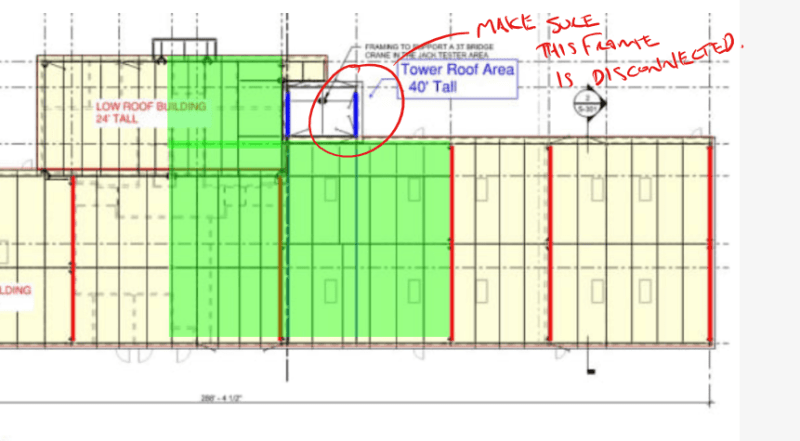
Samwise, you don't seem to meet the code requirements to utilize the flexible diaphragm assumption, and it feels like you`re really struggling to let go of that assumption. I suggest that you model everything as semi rigid and accept those results, or phyiscally separate the tower as Canwest suggested.

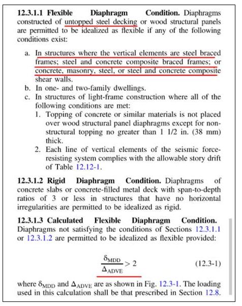
If you take a look at 12.3.1.3, what is says is that when your diaphragm deflects twice as much as the average of your frames, you can assume flexible behaviour.
KootK said:
A flexible diaphragm on rigid VLFRS begets a diaphragm that behaves flexibly analytically.
Correct. The diaphragm is more much flexible that the frames, therefore flexible is appropriate.

KootK said:
A flexible diaphragm on a flexible VLFRS begets a diaphragm that behaves rigidly analytically.
I wouldn't say this is rigid behaviour, but the diaphragm is not flexible in this case. Both the stiffness of the diaphragm and the stiffness of the braces frames are important, therefore, a semirgid analysis that considers all of this is necessary. I think RAM SS is a good program for this effort.

nobody said:
A stiff diaphragm on a flexible VLFRS behaves rigidly analytically.
In this case load a rigid analysis is appropriate and load distributed based primarily on the stiffness of the VLRFS elements.

Samwise said:
...a semi-rigid analysis to get the braced frame force. Did you mean to say semi-rigid for moment frame force ?
Nope, I said it correctly. A semi rigid analysis is the most appropriate analysis to use, however, it sometimes predicts very low forces in the moment frame elements due to their low stiffness. Sometimes I will use a flexible analysis and envelope the two results in order to get higher design forces in the braced frames, that "feel" more correct to me. I would not use this methodology to lower the results of either analysis type.

Clearly you want less load in your tower - have you tried increasing the stiffness of your moment frames? The stiffer they get, they more load they`ll attract.
 
Once20036 said:
I do not want to make the braced frames more stiff as they will attract more load into the tower roof. I have moment frames elsewhere.
Also , the ASCE 12.3.1.3 provisions are for seismic loading. My seismic loads do not govern.

What is the stipulation for diaphragm to behave as flexible with respect to wind loads. I don't think we can use the ASCE 12.3.1.3 right ?
 
Celt83 said:
Based on the deck gage and fastening, using vulcraft tool I can get the G' value. Then I used the equation specified by RAM to calculate the E' value. I calculate this for each bay and averaged the E' value and used that in RAM for the semi-rigid behavior. Is that appropriate ?


1JPG_uwhsiy.jpg


E_tsml3r.jpg
 
Status
Not open for further replies.
Back
Top