Continue to Site

Eng-Tips is the largest engineering community on the Internet

Intelligent Work Forums for Engineering Professionals

  • Congratulations KootK on being selected by the Eng-Tips community for having the most helpful posts in the forums last week. Way to Go!

diaphragm transfer 1

Status
Not open for further replies.

struct_eeyore

Structural
Feb 21, 2017
253
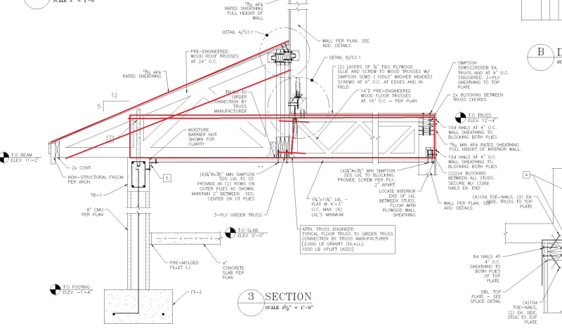
I've got this bastard of a condition where a second floor wood frame bearing/shear wall terminates above open space below (see attached pdf). Presently, I've got a girder truss that supports independent floor and roof jack-trusses, and I'm bearing the wall in question on the inside of the GT, right at the tip of the floor trusses. Being unsure of how well this will work, I've also added a series of LVL's underneath, flatwise, secured to the underside of the GT to take any unresolved shear directly to shearwalls on either side.

I'm looking for any and all critique as this is becoming a detailing nightmare - I've been staring at this long enough that I'm not sure I'm missing something. Also looking for suggestions to simplify things, as the carpenters in my area are notorious for not following the drawings.


[URL unfurl="true"]https://res.cloudinary.com/engineering-com/image/upload/v1715118841/tips/truss_wnudfk.pdf[/url]

edit: subject
 
Replies continue below

Recommended for you

I have no direct help for your question. But I did want to comment that your drawing detailing looks good. Is that just AutoCAD or similar, or something more advanced?

(Also I notice there have been quite a number of diaphragm questions being asked recently, good to see such questions raised and the resulting discussions.)
 
@human909 - I use BricsCad - it's effectively an AutoCad clone, but they still sell perpetual licenses for $600 a pop.
 
Any reason your floor trusses can't span all the way to the external wall? Does it increase span too much? If they could make it then the lower roof could be just built over these trusses.
I know this doesn't solve the diaphragm shear issue, but just a thought as to eradicate complicated connections to girder and the girder itself.
As for the shear, what ceiling sheeting is below? as I imagine the ceiling diaphragm would be alot stiffer that the LVL. Just a matter of providing boundary nailing/fixing at transfer from floor to ceiling diaphragm with full height blocking.
 
First off, nice details.

This looks kinda tricky. If nothing else, might it be easier to just sheathe the ceiling rather than use LVLs, or would that create a nightmare in terms of ceiling access?

In general, what does the floor plan look like? Is Section 3 typical for that entire side? What are the dimensions from outside wall to girder truss to interior wall? Is the girder truss supported with interior columns? Just trying to understand the problem better. Not sure I'll come up with much, but I'll give it a try. I feel like I'm often trying to detail similar nonsense.
 
@Toby43 -

1) Continuous trusses were a consideration, but around my neck of the woods, floor trusses are made with flat chords, while roof trusses are vertical. I just might have to contact a local supplier and see if this can be done.

2) No ceiling sheathing. It will be drop ceiling - of course [evil]
 
It's getting late and I might be losing cognitive function, but I want to say that this might work, more or less as is, if the diaphragm unit shear force can be transferred from the floor, into the girder truss (or into the sheathing along the side of it) and into the roof diaphragm. Due to the vertical offset in the floor and roof diaphragms, there would be a resultant vertical force at that junction, but presumably this can be resisted by the girder truss, being that it's designed to resist vertical loads anyway. Also, the diaphragm chord forces resisting tension/compression at the near and far ends of the diaphragm (out of and into the page relative to Section 3) will also need some sort of vertical element (column) capable of transferring this axial force due to the offset. Contingent on those things being accounted for, I think this can work.

As a side note, to ensure the shear force from the roof diaphragm gets into the exterior wall, I would probably add either (1) blocking above the exterior wall up to the roof sheathing or (2) sheathe the underside of the roof overhang.

I would need to reflect on this in the morning to better determine if this idea is wacked, but right now it seems to make sense.
 
I commend your dedication to a complete load path in the details - some of which would likely make me quite lonely in my locale.

The idea in general can work, the roof and floor diaphragm are treated as one - the vertical offset in the chord members need to be accounted for which perhaps can be done with the HGA and ceiling LVL, though these would only need to be at the chord locations. The vertical force as a resultant of the net shear at the step location also as Eng16080 indicates. I would follow Terry Malone's guidance on diaphragms with vertical offsets as much as I practically could.
 
I hope I understand your question. I had something similar. I would continue the diaphragm to the exterior wall and stick frame the lower roof. Would this work?
Screenshot_2024-05-08_212438_c0hhif.jpg
 
@DoubleStud - I do like this idea, and it does simplify construction. Hopefully the truss manufacturer doesn't kick it back due to the point load from the wall
 
Status
Not open for further replies.

Part and Inventory Search

Sponsor