Continue to Site

Eng-Tips is the largest engineering community on the Internet

Intelligent Work Forums for Engineering Professionals

  • Congratulations KootK on being selected by the Eng-Tips community for having the most helpful posts in the forums last week. Way to Go!

Diaphragms and Rigidity question

Status
Not open for further replies.

ENGR_2321

Structural
May 9, 2017
35
Hi everyone. I was working on a problem from the IBC Structural /Seismic Design Manual and I have two questions I am wondering if anyone know, your answer would be appreciated. here goes:

1) when considering torsional and direct shear , is the torsional moment always assumed counter clockwise? The code and this example do not say anything on this. The example in this book uses counter clockwise and the only explanation it offers is that "the seismic force V applied at the center of mass CM is equivalent to having a V applied at the CR center of rigidity together with a counter clockwise torsion T." I don't know if its always counter clockwise though? it matters to because it affects the signs of a lot of the calculations I have to do after, like when calculating the amplification factor.

2) when calculating the torsional shears (the ones for the amplification factor. because there seems to be 2 sets of torsional shear equations, one for when calculating amplification factor and one for when calculating the actual torsional shears), it says we use the e+ e accidental only for both walls in question. NOT the e-e accidental. they use the e- e accidental when calculating the actual torsional shears. but my question is, do we always use the e+ e accidental only when calculating amplification factor ?

thank you I would really appreciate some feed back if anyone knows
 
Replies continue below

Recommended for you

1) Torsion can be in either direction. It adds to direct shear on one side and subtracts from it on the other side.

Suppose we have a beam rotationally fixed at each end and loaded with a concentrated load P at eccentricity e from the center of the beam. The applied torsional moment is P.e and can be clockwise or counter clockwise depending on the direction of eccentricity. The shear at each end, neglecting beam weight is P/2. The torsional moment at each end is Pe/2 and is opposite in direction to the applied moment because it is a reaction. Torsional moment adds to beam shear on the side where the eccentricity lies and subtracts on the opposite side.

2) I will pass on this question as I am not familiar with the IBC Structural/Seismic Design Manual.

BA
 
Hi BA,
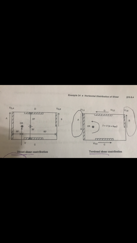
that makes sense but look at how they have it ( I inserted picture of it). If we are following that logic of looking at it like a beam with an eccentric load, then wouldn't it be clockwise ? (based on the picture). I notice they have the arrows of the shear going with (instead of against, like reactions) the torsional moment.

I understand the whole subtracting and adding it based on these directions. I just dont understand why they are going the same as the torsion moment and why that torsional moment is going counter clockwise because its on the left side from the center mass so it would tilt the diaphgram clockwise wouldn't it?

I feel like the wall rigidities and difference in length has to do with it maybe but in this particular example the wall rigidies were given already pre-calculated.

torsional_lxt2ms.png
 
Sorry, I misunderstood your question. We were talking about completely different things. I was talking about applied torsion about the axis of a beam. You are asking about torsion on a building where the end walls are of different length. If Wall A and Wall B were equal in length, there would be no torsion if the applied lateral force was centered between them.

In the current example, the lateral force on the building is directed northward (toward the top), based on the diagram showing the direct shear contribution. Torsion is counterclockwise because the center of the applied force is east of the CR (presumably half way between wall A and B).

If the seismic (or wind) force were reversed i.e. pointing south, the direct shear would be reversed and the torsion would be reversed, i.e. counter clockwise.

If the applied force is F and it occurs 20' east of CR, the moment is 20F, counter clockwise if it's directed north, clockwise if it's directed south.

BA
 
Haha I completely see it now. It's like pinning that CR and and seeing how that F force from the CM will turn it. Yes that makes perfect sense. coming in directed towards south would make it clockwise. In this case, it heading north, hence making it turn counter clockwise. Thank you so much!!!! I wouldn't not have gotten it by myself otherwise. I was doing this example problem all day and this was the only missing piece of the puzzle I needed to understand this kind of analysis. and I knew it was important to know because it affects all the other calculations thereafter. Seriously, THANK you. I owe you a drink or something.
 
The torsion can be either clockwise or counter clockwise the torsion direction depends on the relative location of mass center/stiffness center and the direction of ground movement.
The accidental eccentricity could be either positive or negative (the real distance between mass center and stiffness center can be larger or lesser than the distance calculated), you have to calculate the torsion based on real mass to stiffness center distance is larger than calculated distance
 
Status
Not open for further replies.

Part and Inventory Search

Sponsor