Eng-Tips is the largest engineering community on the Internet

Intelligent Work Forums for Engineering Professionals

Die design question

Status
Not open for further replies.

pancakeglutton

Mechanical
Aug 3, 2023
7
0
0
CA
I'm currently experiencing something I find quite strange on a set of dies I'm working on. These dies are designed to be used on a press brake with a pattern and is located by pins on the apex of the top die in the picture below. The arrows I have on the photo indicate the direction I compensated. What I'm experiencing right now is that on the art, the angle between the flange indicated by the red arrow and the face indicated by the black arrow is smaller than what is on the die. Did I simply compensated the wrong way for the flange? What's going on?

Die_Closed_k6ognu.png


Die_Flange_Angle_znd30j.png
 
Replies continue below

Recommended for you

You're saying the springback in the vee is reversed to what you expected (i.e. the V section is springing back to a narrower section, when you expected it to spring open? Envision the progress of the sheet as the punch drives the metal into the vee - the sheet bends until it eventually hits on the outside edge of the part (the flange edge of the punch) and has to bend down to continue to feed in to the vee as the punch advances. So the sides of the vee have to bend down into the gullet as the press advances, putting a reverse spring-back into the walls of the part before the punch bottoms. If you want to eliminate the issue you could do the part in two hits (vee first then flanges) or make a second die to push the vee back to shape. Though there is probably a way to shape the walls of the vee to compensate as well...
 
Thanks for the quick reply btrueblood! Not quite. The vee is springing open, towards the sides of the die as expected. But the flange seems to be springing towards the bottom of the die.
 
A picture of the formed part profile overlaid on a drawing of the desired shape would help the reader to understand the problem.

The blank is not clamped by anything as the punch pushes the blank into the die cavity. Can you slowly form the part and take some photos of how the blank behaves as it encounters the punch? I think that the blank is striking the punch and bending the material where it should be straight.

What/where is the locating pin you mention? (picture or drawing showing detail) Do you feel that this is in any way influencing the results?

Is the part blank correctly dimensioned to produce the formed part?

 
You should focus on the angel between the V and flanges.
They likely point down because the V is opening.
We used to make some parts that had a similar issue.
We actually made the center of the die separate from the sides.
That way we could fix the center angle and then work on the sides.

= = = = = = = = = = = = = = = = = = = =
P.E. Metallurgy, consulting work welcomed
 
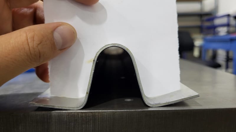
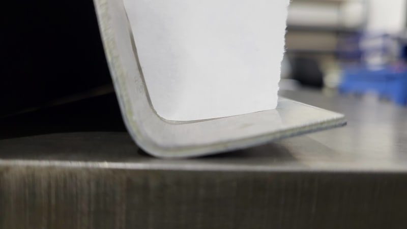
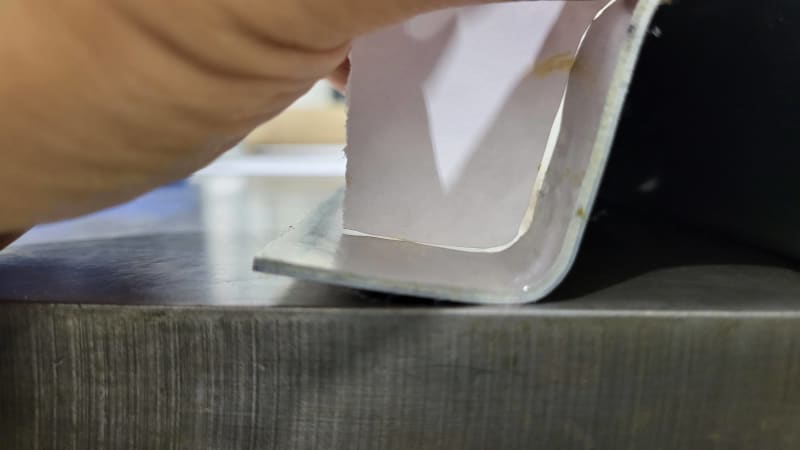
Thanks for the reply, dvd! It is actually a bit hard to line up the profiles, so I've made a paper cutout of the profile. Here's a couple of photos of it on top of the pressed part.

20231026_104547_ombm9n.jpg
20231026_104608_ielevt.jpg
20231026_104616_rrf6vj.jpg


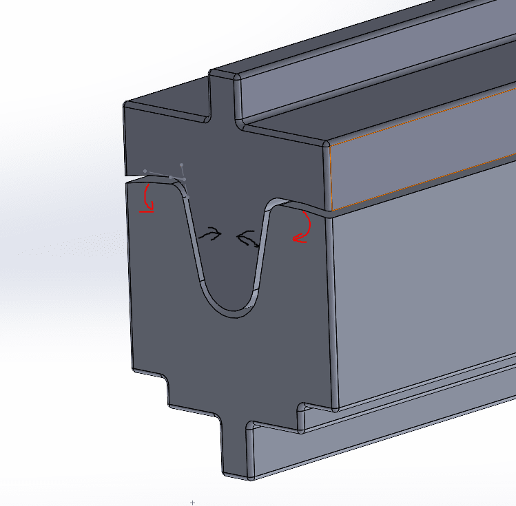
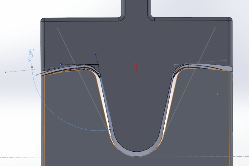
The flange is curved, but the it contacts the ideal profile on the outside first so I take it that the flange is too far up. Although it is also possible that the curvature on the flange is not right. I have also done a laser scan on the part and have found that the flange is indeed too far up.

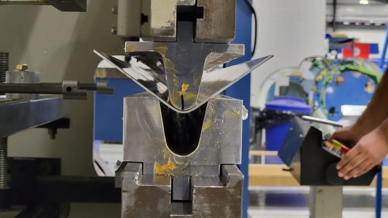
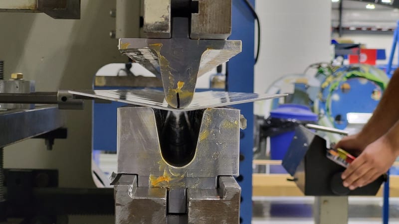
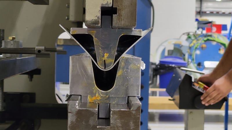
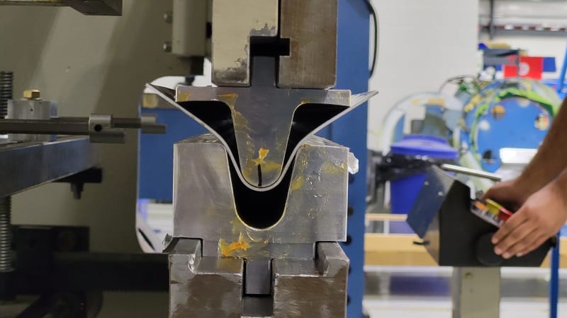
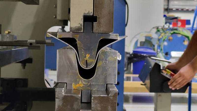
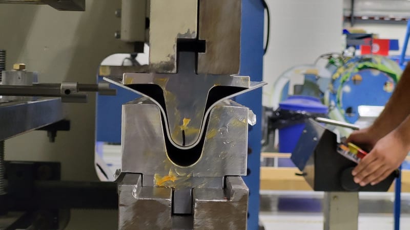
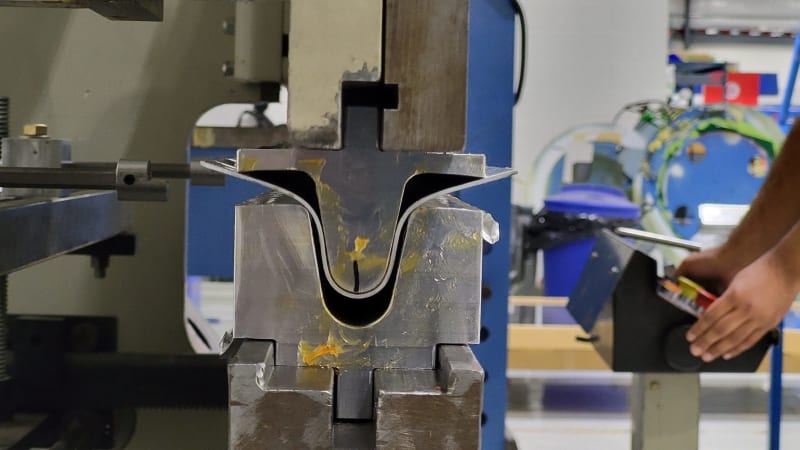
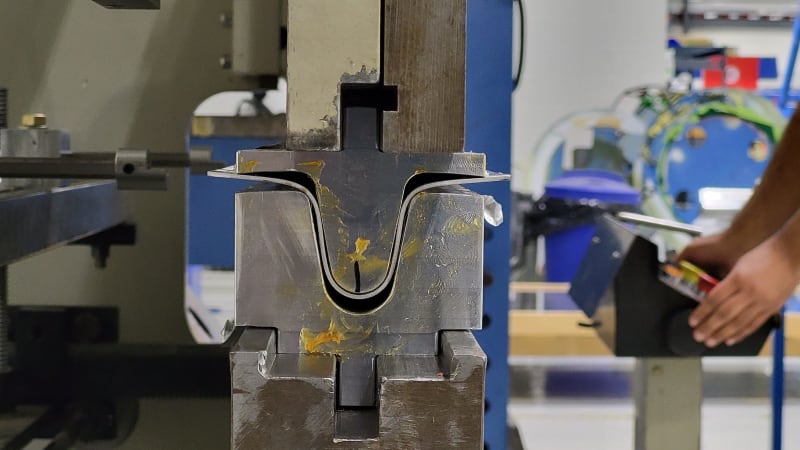
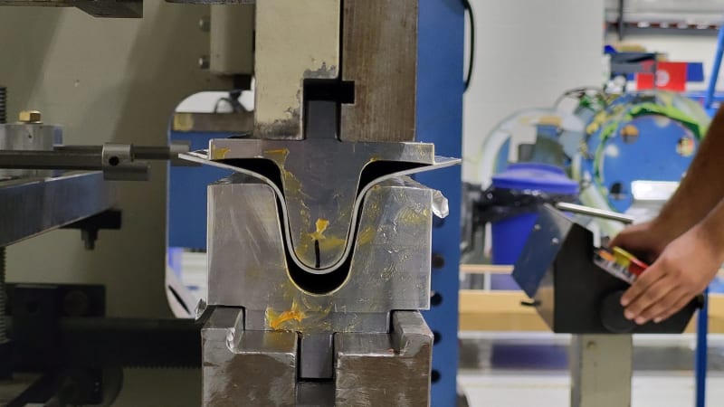
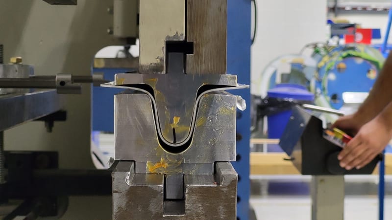
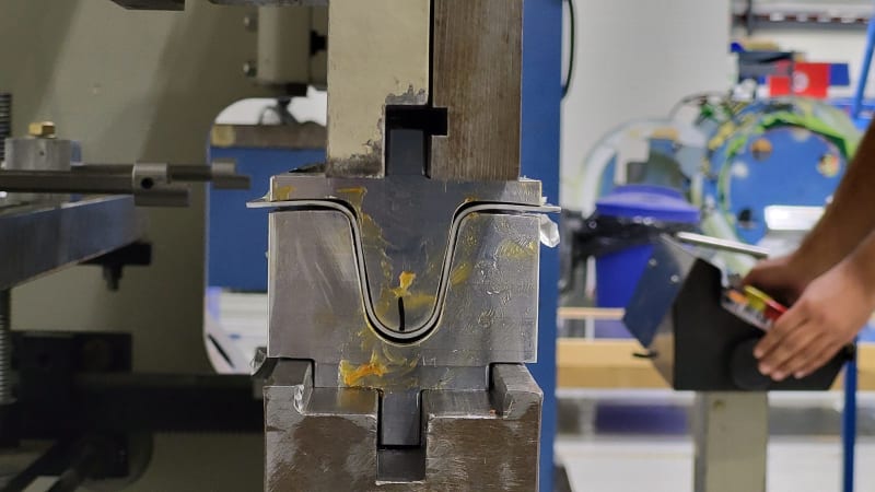
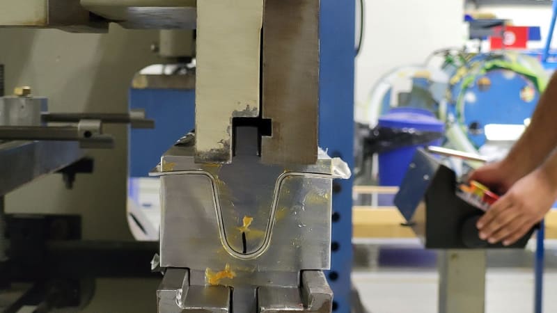
As to the pressing process, I don't have photos of the same set of dies that produced the part that you see, but I do have a set of dies of similar design. Here are some photos of the pressing process.

20231026_111432_upb15u.jpg
20231026_111428_khkks5.jpg
20231026_111435_y58zx1.jpg
20231026_111438_ju0rq3.jpg
20231026_111441_bjtszz.jpg
20231026_111442_ybnhaf.jpg
20231026_111444_fsr4uf.jpg
20231026_111448_0_vqdwr1.jpg
20231026_111446_gxency.jpg
20231026_111448_ydychh.jpg
20231026_111451_fjpypb.jpg
20231026_111515_nazua5.jpg


I will be switching out to the set of dies that was the subject of the original question though so I will take more photos then.

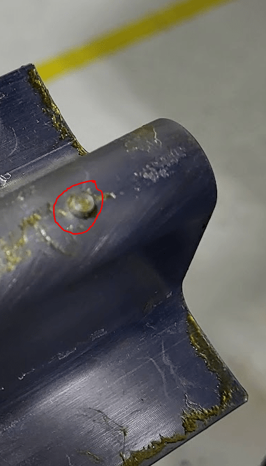
The alignment pins are on the apex of the top doe as shown below. I have corresponding holes on the bottom dies to except the pins, so that they don't make an impression on the bottom die.

Locating_Pin_on_top_die_ztt6oq.png


As to the blank, when the guys pressed that part in the first few photos, they just used an oversized rectangular piece. The pattern that i have designed for the die has widths that is equal to the length of the theoretical neutral line. I have taken the neutral line to be in the middle of the thickness (K=0.5) since the radii are quite large for the thickness, which is 0.071". I'll try and take some photos of that as well.
 
It looks like your punch is contacting the blank and forming a radius in the region where you want a straight section. You might be able to back bump the part after forming to correct this. You've either got to hold the blank flat while the forming punch pushes material into the die, or consider a two-hit forming sequence, where you form both flanges first and then the vee. Either spend more money on tooling or more money on additional operations. Depending on how long the part is, it might be possible to rig up a hold-down that keeps the flanges out of the way of the punch while the vee is being formed.
 
Status
Not open for further replies.
Back
Top