Continue to Site

Eng-Tips is the largest engineering community on the Internet

Intelligent Work Forums for Engineering Professionals

  • Congratulations IDS on being selected by the Eng-Tips community for having the most helpful posts in the forums last week. Way to Go!

Diesel Engine Driven Generator Operation without Cooling Fan 2

Status
Not open for further replies.

FARHANRAZA

Electrical
Dec 20, 2008
13
Dear All Members,
We have been operating a Diesel Engine Driven Generator of following specs:
Generator:
Make: UNELEC France.
Rating:1900 KVA, 1520 KW, 174 Amps, 6.3KV
Diesel Engine:
Type / Model:240-V16-GS-PE-1977
MFG'R: SACM

Recently during startup of Generator after oil change, its cooling fan got damaged. I have following queries:

1. The weight of fan is about 170 kg. Is this fan used for cooling of Generator only or is it used as fly wheel as well.
2. We are going to get this fan casted from local market. In the mean while, is it safe to run the generator in case of emergency requirement by application of external air with an arrangement of hose pipes and external industrial grade fans. Insulation class of Generator stator and rotor windings is B.
3. How can we re-design the fan to make it light weight and less prone to damage, while providing the same cooling air to Generator.
 
Replies continue below

Recommended for you

A photo would be helpful.
At hat weight it may be used as a flywheel or dampener of sorts.
Running with jury rigged cooling could burn up the generator.
And an improper replacement fan could burn it up as well.

= = = = = = = = = = = = = = = = = = = =
P.E. Metallurgy, Plymouth Tube
 
Running the engine at any load, without a rad-fan, will likely cause significant damage to the engine. I dare say you could run for a couple of minutes, without a rad fan, but I would not recommend this as a viable option for any longer duration. Plus, any warranty on the machine will be toast as well, but I suspect you are well past that now.

I would suspect that installing some temporary fans could be made to work under the following conditions;
1) all cooling streams are consdidered (ie jacket-water, lube-oil, intercooler, etc), and
2) the return temperatures are monitored to ensure that they stay within spec, and
3) if the existing rad-fan provides air-flow around the engine for cooling of the engine/alternator, means will be needed to provide this air-flow as well.

You did not mention the engine rpm, but a 170kg fan won't provide any significant inertia, compared to that provided by the engine and alternator.
Are you seriously considering having a local shop cast you a fan impeller? Are there not local radiator/ fan companies who could provide a more standard product?

"I have not failed. I've just found 10,000 ways that won't work." Thomas Alva Edison (1847-1931)

 
Please clarify - are you taking about the engine-mounted fan or the alternator-mounted fan?

I'm intrigued how you managed to damage it and why you think damage is going to happen frequently enough that you should re-design the fan. Diesel generating sets are in use all over the world and you appear to have either an unusually awkward machine to overhaul or unusually poor maintenance techniques. Photos would definitely help us understand what the problem is, and especially if you describe how the damage occurs.

You must be desperate and/or crazy to use a locally-cast fan unless you have balancing and NDT capability and can adequately specify the material and have a first-rate foundry to produce flawless castings. Do you really want to risk a 170kg fan breaking up at 1500 rpm? Buy an OEM part and stay safe.
 
I am talking about alternator mounted fan and not engine radiator fan. This alternator fan got damaged during synchronization with a 10,000 KVA steam turbine generator. We are still in process of finding out exact cause of this damage. This is an old 1977 UNELEC generator and OEM parts are not available. Therefore we have to locally cast the fan. Engine RPM is 1000.

In case of emergency we may have to use this generator for smaller durations (without cooling fan) and for that I wants inputs that can we use it by applying external air sparger & industrial fans & continuously monitoring winding & bearing temperatures?? is it safe? Arrangement for air sparging is attached in pics.


 http://files.engineering.com/getfile.aspx?folder=91df3c51-eead-4152-8b97-7c1a61e88655&file=SAM_0429.JPG
Do your pictures show what you plan to do?

Was the original fan mounted essentially where you're planning to mount this new unit?

Is your temporary air system going to move the air in the same direction through the generator?

If you move the same amount of air in the same direction you can certainly use whatever means you want to move the air. The original method was just the most expedient way.

A separate source could actually be an improvement allowing extended cool down or even increased cooling.

Hopefully you have knowledge of how much air and with what velocity or at least what force it presented, to give you a feel for the effectiveness of your new system. You should be able to test this new system without even running the generator.

Indeed, do monitor the temperature and watch it closely until you have proven its capability in removing the heat and definitely at full generator loading.

One negative of a separate fan is if it is not directly driven by the rotor shaft then that means it could conceivably not run at all while the generator is running. Perhaps a tripped overload, bad contactor, idiot and the switch, a dead motor, frozen bearing, etc, etc. This means you need to include an over-temperature limit alarm unit that disconnects the generator from the load in the event of an approaching over temperature event. The alternative is a destroyed generator at the least and major fire at the worst.


Keith Cress
kcress -
 
That picture helps immensely - it isn't what I had envisaged your problem to be. My opinion would be to fabricate the fan from sheet / plate rather than attempt to cast a fan of this size - you will have far better control of the key performance characteristics and the resulting fan should, if correctly manufactured, be both stronger and more efficient than the cast fan.

I agree with Keith - if the proposed temporary solution moves an equivalent volume of cooling air through the fins then it will work. The key will be ensuring that the airflow passes through the fins, which may require some form of ductwork or cowling. Make sure you make use of the stator RTD's to monitor , and ideally trip, the machine in the event of serious overheating.

Check if this is a thermal Class B or Class F winding. It is common for machines to be built using Class F materials but operated within the Class B limits to ensure a long operating life for the insulation system: you may have a lot more operating margin than you think provided that you are prepared to sacrifice some long-term operational life by running near the Class F limit.
 
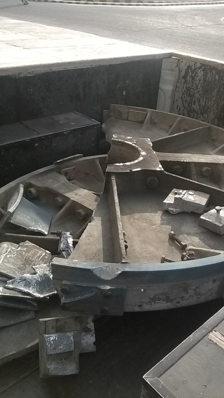
This is the damaged fan which was connected on driven end of generator. Can anyone comment is it only cooling fan or flywheel as well??


WP_20161216_08_53_10_Smart_sfhzxn.jpg
 
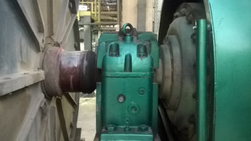
This is the location of fan originally installed on alternator near coupling.


WP_20161220_17_36_20_Pro_eql8v7.jpg
 
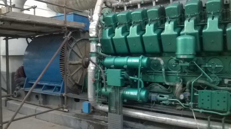
This picture shows air hose pipe connected to air sparger system. Please give your suggestion on this, after that we will try this on load.

WhatsApp_Image_2016-12-20_at_20.37.47_obi5wd.jpg
 
This machine is coming up to the 40 year old mark. Unless it has been rewound lately I would treat it gently.
I would be contacting fan manufacturers to see if an off the shelf fan is available with similar performance specs. It may be easier to modify the drive hub than to fabricate a fan from scratch.
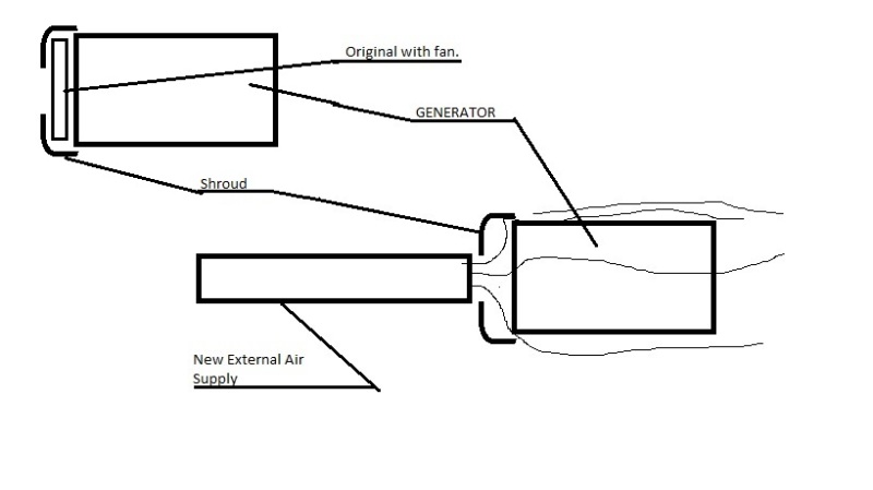
You may want to add some shrouding to direct the air between the fins.
Possibly the original fan had a shroud that may still be used.
Simply direct the air supply to the opening where the air was originally drawn into the fan.
It may be safer and cheaper to forget the fan and use the external air supply permanently.
As long as there is enough air flow in the proper place to keep the generator cool, the generator will not care where the air comes from.

GENERATOR_COOLING_nnev2u.jpg


Bill
--------------------
"Why not the best?"
Jimmy Carter
 
I don't think the sparge pipe arrangement is going to move air in the volume you require. If you want to use compressed air as the air source then you might get better results using multiple venturi-type air movers which use high pressure, low volume air to move high volumes of low pressure air, or possibly it would be easier to just use electrically-driven blowers. Either way you need some sort of cowling or shroud to form a plenum to direct air where you want it - through the fins.

It must have been a scary moment when that fan broke up, I hope no one was hurt. It's a odd-looking fan design. I wonder if it 'sucks' air through the fins?
 
I hadn't seen the latest pictures when I was composing my last post.
Hi Scotty. I would go with a blower and cowling as you suggest.


Bill
--------------------
"Why not the best?"
Jimmy Carter
 
If the fan damage was due to (faulty) synchronizing, as you say, then you must be careful with the integrity of the remainder of the generating set components. Generating sets are designed to withstand the torques resulting from short circuits, not "faulty" or out of phase synchronizing, where the torques are much higher than those from short circuits.

You should look for damage to couplings, stator and rotor windings of the generator and even the crankshaft etc of the engine.

Replacing the generator fan may not fully repair the damage.
 
I don't see using that compressed air system as working at all. You need lots of mass moving between every single fin or you will get very uneven cooling with extremely hot spots between less hot spots and all the uneven damaging thermal expansion that goes with that.

That original 'fan' is really nasty looking. I see why you have concerns that it might also be a flywheel. That outer rim that looks completely counter to air flow and adds greatly to that structure's moment of inertia. It's still probably not a needed flywheel.

I think any of several different fan setups could actually be better. I'd consider finding a very large air handler preferably used or discarded and set it up next to the generator with a simple, big, U shaped duct that would tightly seal it to end face of the generator. The duct work could even be well built (ply)wood if expedience is required.

Alternatively a large axial fan that is completely shrouded would also do the job.

If you absolutely must use compressed air you need to refine that design considerably. As Scotty was saying you need to us a venturi outside the U of each and every fin pair that entrains air caused by the nozzles, thereby quadrupling the actual air (mass) being propelled down each channel. That will likely require far more air than you're going to get in thru that one measly inlet. I'd guess 100PSI air through 1" airlines in no less than about 4 inlets with venturies would maybe be enough. That's about 140 venturies! That's why they used a blower instead.


Keith Cress
kcress -
 
The more I look at the wrecked fan the more I think we can only see the rear face of the fan disc complete with stiffening ribs. The side hidden from view must have been provided with radial blades like those fitted to pretty much all TEFC machines. Presumably these have been smashed off during the event? If the fan is aluminium then I doubt it was intended as a flywheel.

Hoxton makes a very good point about residual damage to the machine caused by the crash synchronisation. At least is a relatively small machine so the forces are relatively low. Similar events on large sets have caused spectacular problems. You should certainly consider an inspection of the areas mentioned by Hoxton. I would add con-rods (still straight?) and foundation anchor bolts as things to check for damage.
 
Status
Not open for further replies.

Part and Inventory Search

Sponsor