Continue to Site

Eng-Tips is the largest engineering community on the Internet

Intelligent Work Forums for Engineering Professionals

  • Congratulations KootK on being selected by the Eng-Tips community for having the most helpful posts in the forums last week. Way to Go!

Difference between axial total runout and perpendicularity

Status
Not open for further replies.

semiond

Mechanical
Jan 9, 2011
176
Hi all,
A part is consisted of two coaxial cylindrical features. Is there any difference between the following callouts:

1. Perpendicularity on the end face of one of the features to a datum axis of the other feature.
2. Total axial runout on the same end face to the datum axis.

In terms of the tolerance zone shape, it looks like they are the same, but i might be missing something?
 
Replies continue below

Recommended for you

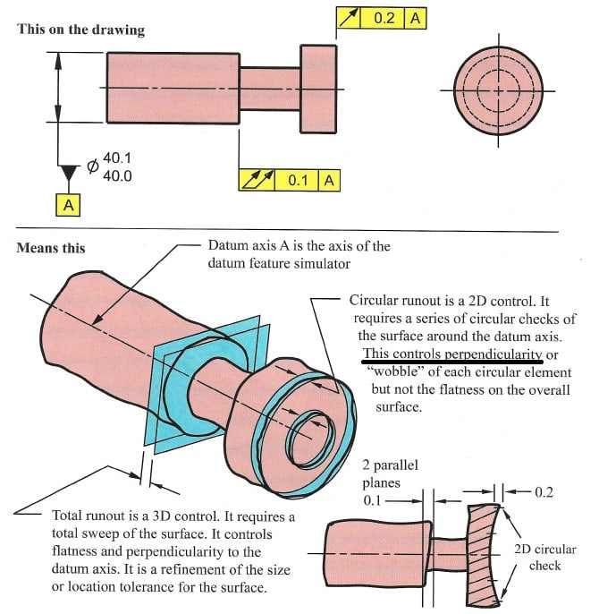
Will it make you confused on the snapshot (from a textbook) "Means this"? As highlighted below---This controls perpendicularity.

2018-05-31_101951_opovs3.jpg


Season
 
Not confusing enough.
You underlined the beginning of the sentence, i would underline the continuation instead: "of each circular element". With that in mind remember what i said earlier about a conical surface, this should complete the picture.
 
Season,
The book does not say the perpendicularity of the SURFACE. A minor but very important detail. The OP clearly states "end face". For me "end face" means surface. Not elements (liniar or circular elements) of that feature.
 
Season,
I think my previous explanation with the comparison to conical surface needs clarification. A conical surface that was designed and intended that way can also have very good total runout, when measured normal to the surface.
What i meant is a surface that was intended to be flat and was made slightly conical (becauae of a machinist's error at turning for example). Runout would be measured in the axial direction. The circular runout may still be very good, but the total runout will be bad, and the perpendicularity of the surface to the axis will also be bad. The total runout reading will directly represent the out-of-perpendicularity condition.
 
semiond - i agree your description of circular vs. total runout, i wish there was a video of some sort that showed what you are describing as i think it would go a long way in getting the point across and most graphic representations of it do a poor job. i did a brief search but didn't find anything that showed the exact situation you described.

i also think the wording in the standard on total runout is unfortunate as in 9.4.2.2 it says "total runout controls cumulative variations of perpendicularity (to detect wobble) and flatness (to detect concavity or convexity)" - i understand what they are trying to say however it suggests that total runout controls flatness differently/to a greater degree than perpendicularity which is not the case.

semiond said:
A conical surface that was designed and intended that way can also have very good total runout, when measured normal to the surface.

as an additional question, can someone clarify whether this is the case - that total runout can be applied to conical and curved features (see the graphic below)? the wording in 9.4.2.1 seems to support it and besides being more difficult to measure with a traditional dial indicator (or maybe impossible - in the case of complex curved surfaces) i can't see any reason why this wouldn't be theoretically allowed, however none of the examples in the standard show this. total runout is only shown in the examples on perpendicular or cylindrical surfaces.

EDIT: i should clarify - i mean more difficult to measure total runout of conical and curved surfaces with a traditional dial indicator setup only, it should be relatively simple to measure on a CMM

total_runout_orwgt8.png
 
chez311 said:
suggests that total runout controls flatness differently/to a greater degree than perpendicularity

Perpendicularity tolerance zone is constrained by two parallel planes. Flatness tolerance zone is constrained by two parallel planes. Total runout tolerance zone is constrained by two parallel planes.
We have a tendency to over-complicate things.

chez311 said:
can someone clarify whether this is the case - that total runout can be applied to conical and curved features

To curved features - no. To conical features - Y14.5 has Para. 9.4.2.1 that says: "Where applied to the surfaces, constructed around a datum axis, total runout may be used to control ... angularity, taper ...", but they don't back it with picture.

In ISO total runout is ONLY applied to cylindrical and flat axial surfaces.

Edit: I added reference to clarify ISO view of total runout:
"For every expert there is an equal and opposite expert"
Arthur C. Clarke Profiles of the future
 
chez311,

I agree that the application of total runout to conical and curved surfaces is limited by meaasurement practicality and not by any fundamental issue. It is possible to measure this with a dial indicator, just difficult (there would have to be a mechanism to track the indicator along an angled or curved path). It is also possible to measure it with a CMM.

Interestingly, USAS Y14.5-1966 includes examples (with figures) of total runout applied to conical and curved geometry. At some point (I'm not sure if it was the 1974 or 1982 standard) Y14.5 decided that this was to be avoided, and since then has only dealt with circular runout on cones and curves.

Evan Janeshewski

Axymetrix Quality Engineering Inc.
 
And to go even further, and add on Evan's history about total runout on cones I would say that in the next revision of y14.5 (now draft) total runout on cones will be forbiden. Am I correct Evan?
Somewhere in the draft they have added that total runout shall control cylindricity.
That implies at least in my opinion that total runout on a cone becomes no-no in the future.
What do you think Evan?
 
greenimi,

As far as I remember, the new draft doesn't forbid total runout on cones and curved surfaces. It just doesn't mention it. The descriptions and figures for surfaces constructed around a datum axis only mention cylindrical surfaces and not cones and curves. You're also correct that the description of what types of variation are controlled was changed, to add cylindricity (and remove angularity and profile of a surface, which were incorrect). This (to me) heavily implies that the intent is to confine it to cylinders, but it doesn't explicitly state that. So the debate over whether not applying total runout to cones and curves is "legal" will likely continue. Sigh.

However, this debate will less relevant for the new version of Y14.5. The dynamic profile tolerance modifier, when applied to conical or curved surfaces of revolution, can define a tolerance zone identical to what a total runout tolerance would define. So the "legality" of total runout on cones and curves becomes a moot point - you will be able to use dynamic profile to accomplish the same thing.

Evan Janeshewski

Axymetrix Quality Engineering Inc.
 
greenimi said:
Somewhere in the draft they have added that total runout shall control cylindricity.
We discussed that on another thread and in the end all agreed that total runout in relation to a cylindrical feature's own axis and cylindricity are not the same thing.
The people who write the standard should read this forum[wink]
 
axym said:
It is possible to measure this with a dial indicator, just difficult (there would have to be a mechanism to track the indicator along an angled or curved path).
I suppose the inspectors could try to orient the part according the conical taper angle, to bring it to a condition where the upper part of the silhuette of the conical feature appears horizontal and parallel to the inspection table, making an optimization of sorts, and check it in rotation with the dial indicator like it was a cylinder.
 
axym said:
However, this debate will less relevant for the new version of Y14.5. The dynamic profile tolerance modifier, when applied to conical or curved surfaces of revolution, can define a tolerance zone identical to what a total runout tolerance would define.

Im very interested in the prospect of a dynamic profile tolerance - I don't know all the details from your description it seems like a very versatile control that accomplishes things I sometimes find myself wishing profile would accomplish currently.

In the meantime - is there any recourse through the current 2009 standard that would create an equivalent tolerance zone as total runout on a conical/curved surface without using the total runout symbol and creating downstream confusion and arguments about legality of its use? I'm sort of drawing a blank right now trying to come up with something.
 
chez311,

What application have you got that requires precise control of the profile of the part without much care for the actual local diameters? Per 2009, figure 8-27, you can combine profile of a line and directly toleranced dimensions. Since everyone is big on 'extension of principle' then it seems like profile of a surface would also be applicable; profile of a surface is applicable to a revolved surface as shown in 2009, figure 8-26.
 
Evan et al., here's a link to a previous thread where we discussed total runout on a cone. The consensus seemed to be that it's OK, although there was banter about having the dial indicator be normal to the surface:
[URL unfurl="true"]https://www.eng-tips.com/viewthread.cfm?qid=315985[/url]

John-Paul Belanger
Certified Sr. GD&T Professional
Geometric Learning Systems
 
3DDave - I can't specifically think of an application at the moment, however if that were the case total runout wouldn't be as useful a control as it is. Perhaps there is an irregularly shaped feature that requires balancing - I'm not sure exactly the effect of circular vs. total runout on balance but I have to imagine total runout would be a tighter control, especially over longer lengths.

Anyway thank you for pointing out that figure - I was not aware profile could be applied to directly toleranced dimensions. Indeed, after seeing that I also found Figure 8-18 which show profile of a surface with an axis datum reference applied to a conical profile with a directly toleranced size dimension which should accomplish the same thing as total runout on a cone/taper. I'm not so sure though if one could successfully apply this to an irregular surface (ie: non cylindrical/conical) - it would be very sensitive to how basic/toleranced dimensions were applied and I think it would probably be a nightmare to inspect.
 
Status
Not open for further replies.

Part and Inventory Search

Sponsor