Continue to Site

Eng-Tips is the largest engineering community on the Internet

Intelligent Work Forums for Engineering Professionals

  • Congratulations KootK on being selected by the Eng-Tips community for having the most helpful posts in the forums last week. Way to Go!

Difference in SF1 and SF2, ABAQUS

Status
Not open for further replies.

Arnaud De Coster

Civil/Environmental
Nov 29, 2023
2
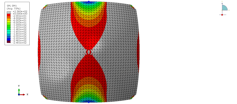
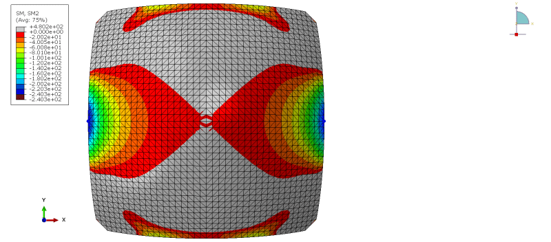
SQUARE_SM2_BLUE_bis_pp3lxt.png
SQUARE_SM1_BLUE_bis_vlmwhk.png


Hi everyone,

I am analysing a double symmetrical (domed) shell in Abaqus and what confuses me are the differences in the SF1/SF2 plots as well as SM1/SM2 plots.
In the plots visualised with this message you can see the sagging moments in both directions. Unfortunately, the plots are different which is quite confusing as the structure is double symmetrical.

If I'm not mistaken:
SF1/SF2 are the direct membrane forces per unit width in local 1-direction/2-direction.
SM1/SM2 are the bending moment forces per unit width about local 1-axis/2-axis.

The shell is meshed with quadratic triangular thin elements (STRI65: six-node triangular thin shell, using five degrees of freedom per node) with an edge size of approximately 0.2 m.

Thank you in advance,
Cheers,
Arnaud
 
Replies continue below

Recommended for you

Arnaud De Coster said:
If I'm not mistaken:
SF1/SF2 are the direct membrane forces per unit width in local 1-direction/2-direction.
SM1/SM2 are the bending moment forces per unit width about local 1-axis/2-axis.

That's right, it's described in the "Three-Dimensional Conventional Shell Element Library" chapter of the documentation. Local directions in shells can be quite tricky due to the projection done by Abaqus. But what about the other outputs like stresses/strains and so on ?
 
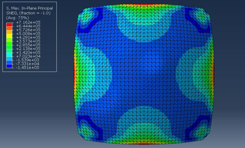
stress1_ecarsu.jpg
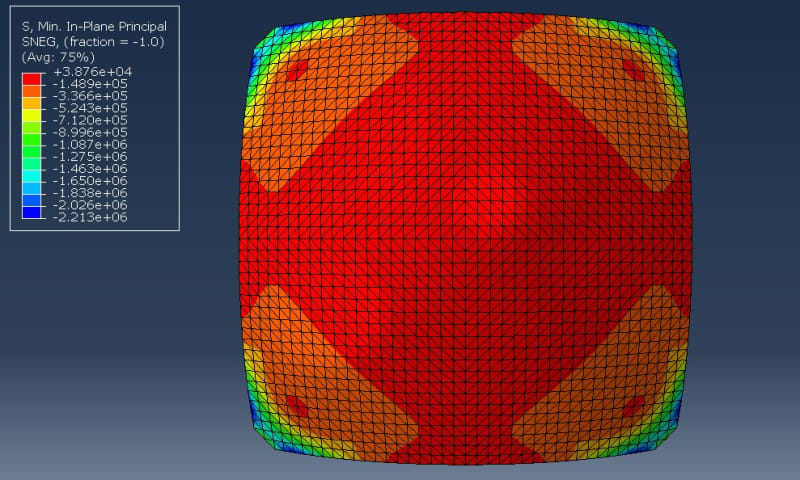
stress2_dvypgy.jpg


Thank you for your response.

Concerning the stresses and strains, the plots are completely symmetrical.
In here, I posted two images of the max and min in-plane principal stresses, to get a better view.

Cheers,
Arnaud
 
It could be helpful to create a symbol plot of material orientations of those shell elements to identify the axes corresponding to those SF1/SF2 and SM1/SM2 outputs.
 
Status
Not open for further replies.

Part and Inventory Search

Sponsor