Eng-Tips is the largest engineering community on the Internet

Intelligent Work Forums for Engineering Professionals

Different Buckling load Factors for Same Model, Different Software 3

Status
Not open for further replies.

Doodler3D

Mechanical
Jan 20, 2020
188
0
16
US
Hi,

I'm practicing the ASME PTB-3 example 5.4. I get different values of the buckling load factor for the model (8 node shell elements). Any hints as to why this is happening?

Nei Nastran Inventor = 14.655
Solidworks = 15.587
Ansys Workbench = 11.954 (matches PTB-3 Result, minus the load factor)

Thank you

Screenshot_1_hrhba4.png
 
Replies continue below

Recommended for you

Make sure that there are no differences in settings such as load, material model, and so on. If you can’t use the same mesh (generated in the same preprocessor) for all analyses then try to recreate it as accurately as possible (take a closer look at local refinements if you use those). If you still get slightly different results then it’s probably due to differences in formulations and algorithms used in each of these programs. It’s very common that there are some small discrepancies in results when comparing various solvers.
 
I have seen this, too, with absolutely identical models between ABAQUS and ANSYS. The eigenvalue buckling results are different between the two software. I took extreme precautions to ensure that the models were identical.
 
@All. Thank you. I believe it has something to do with the iteration schemes and contact between the skirt and the vessel. In Ansys, one must manually define the contact edges while Nei Inventor Nastran creates a continuous, conformal mesh that does not need contact definition. SW has triangular elements (so I'm leaving it out of the discussion), others have 8-node quads. Beyond that all models were set up with identical material, mesh size and BCs. However, I do not know how to interpret the buckling load factor showing ~ 20-30% difference.
 
If you plot the lowest buckling mode shape in each analysis application with an exaggerated amplitude (and / or colour contour and animation), you will be able to compare the mode shapes that are computed. You may find for example that subtle differences in applied support boundary conditions (simple support vs fully fixed) can change the buckling mode shape and load factor significantly. When all analysis packages show the same buckling mode shape, you would expect the buckling load factors to be very similar.

 
@ IDS, its ASME PTB-3 example 5.4.

From ASME PTB-3

Evaluate the following tower, Figure E5.4-1, for compliance with respect to the Type-1 buckling criteria provided in paragraph 5.4.1.2.
[ul]
[li] Material – Shell and Heads = SA-516, Grade 70, Normalized[/li]
[li] Design Conditions = -14.7 psig at 300oF[/li]
[li] Corrosion Allowance = 0.125 inches[/li]
[/ul]

Attached: STEP file.

Screenshot_292_skjhnz.png
 
there seems to be something wrong with your download link for the STEP file. I'm not able to download. Can you check and re-upload from your side?
 
I wonder if the solution is from an ANSYS FEA and no one looked at other codes ?

Do the mode shapes look similar ?

Is there a "right" hand book solution ? Are we talking about buckling of an unpressurised cylinder ?

4" element size is small compared to the tank dimensions, but not that small compared to the thickness (1.125").
I wonder about 20 node Brick 3D elements ?

another day in paradise, or is paradise one day closer ?
 
Okay.

I have some first pass results done using MSC.Nastran. Used a 4-noded cquad4 shell element of size 2.5inches for a linear buckling analysis. Per the ASME example the static pressure load is treated as a pre-load for the buckling case and the buckling factors are calc'ed. The lowest eigenvalue (buckling load factor) is 10.918. I don't think the results using a cquad8 would be that different, but I'll give it a stab tomorrow (it's already past midnight my time!!). Here attached to this post is the mode-shape corresponding to the lowest eigenvalue.

buckling_asme_d2i5n6.jpg
 
@nlgyro, thanks for taking a look. The mode shapes are probably going to be the same. I assumed that the PTB-3 is close to a benchmark, but there appears to be a lot of errors in the 2013 edition.
 
Did the analysis using cquad8 elements with an element size of 2.5 inches. The lowest eigenvalue is 10.902 (10.918 using 4-noded elements of 2.5in size). The procedure is the same. Attached is the mode-shape corresponding to the lowest eigenvalue.

ASME_Pressure_Vessel_Buckling_cquad8_nnrcxx.jpg


The static preload (obviously) has a big influence on the analysis. Without the use of preload and doing a regular linear buckling analysis the lowest eigenvalue is 11.902 which closely matches your ANSYS results (11.954). ASME ptb-3 (2013 edition) treats the external pressure load as a preloads to calc the buckling factor and thats what precisely been done in my models. I obviously can't vouch for the veracity of the 2013 edition as this is not something I use for my field of work day-in and day-out!! The mode-shapes that I have plotted above are identical to the shapes given in ASME ptb-3.

Coming back to you original question. You did mention contacts in your ANSYS model. Are you running it non-linear?? Or is your ANSYS run just a linear buckling analysis??Are you defining external pressure load as a static preload in your models across all packages you have used?? Are you sure that 8-noded shell is supported in a buckling analysis for inventor nastran?? You have discounted the SW results on account of its use of trias, so when compared with inventor nastran and the difference that you vis-a-vis ANSYS your answers to the above questions could provide some insight.
 
I was able to get some computing time at a local university over the weekend that uses Inventor Nastran 2020.
To check the validity of the code for buckling I took a problem that can be hand calc'ed.
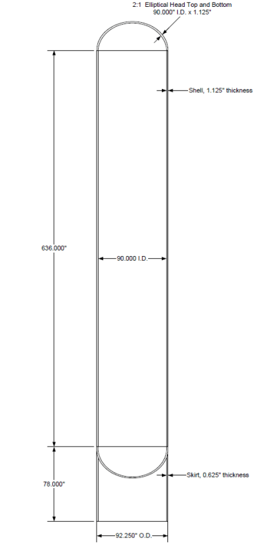
I took the same example as your ASME pressure vessel, removed the elliptical heads replaced them with flat end-plates, and removed the skirt.
So essentially the model is a cylinder with flat end-plates. I loaded it with an overall external pressure and used a 'classical' simple support condition at the ends.
Steel is used as the material.
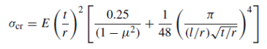
The critical buckling stress is provided in Rotter's text chapter 5 eq(8)

critical_buckling_Stress_fypokv.png


Here is the summary of the hand-calc

E = 2.90E+07 psi
nu = 0.3
t = 1.125 in
r = 45.563 in
L = 636 in
Z = 7527.918
L/r = 13.959
Scr = 6407.300 psi
Pcr = 158.205 psi

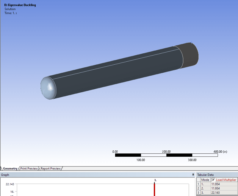
Modeled the problem in both MSC.Nastran and Autodesk Nastran using 4-noded CQUAD4 shell elements of element size 2.5 inches.
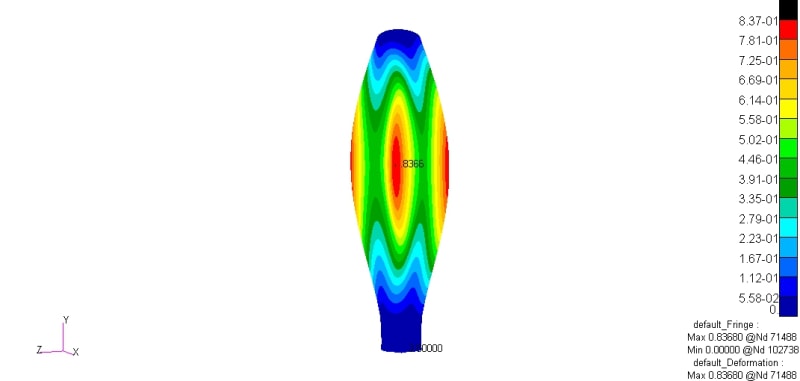
Ran a linear buckling analysis and here are the results:

Pcr (Theory) = 158.205 psi
Pcr(MSC.Nastran) = 159.870 psi
Pcr (Inventor) = 211.120 psi

% difference Pcr(FEA) / Pcr(Theory)

MSC.Nastran = +1%
Inventor Nastran = +33%

So there is your +30% that you were talking about in your earlier posts. For a simple test problem Inventor over-estimates the buckling pressure/stress by +30%.
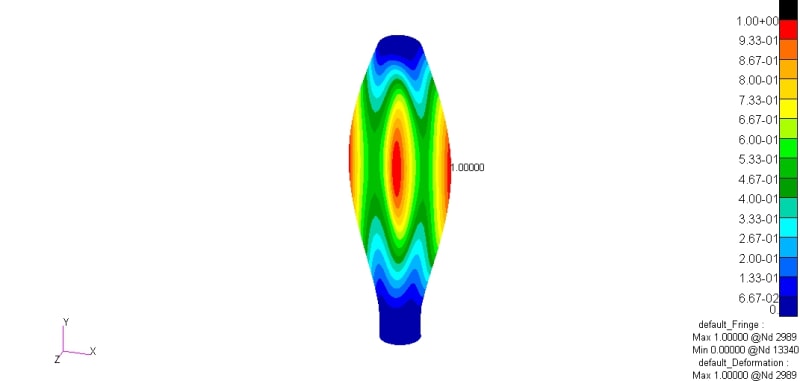
The static analysis b/w both codes are identical. Peak deflection is at the flat end-plates. Both codes register 0.022in as the peak deflection under 1psi pressure.
So there is something going wrong in the buckling solution in Inventor. Maybe the differential stiffness formulation is a suspect or the implementation of eigenvalue solver
is a suspect. But if I were you I would junk this code as it can't predict a classical hand calc'ed problem!
I don't have access to ANSYS but it’s a well respected code in the industry so I wouldn't expect it to misbehave for such problems.
 
@nlgyro Thank you for taking a detailed look at the problem. FEMAP, too, predicted a linear buckling load factor that was closer to ANSYS (linear). There's certainly something dubious about Inventor Nastran. Also, the book you referred to is 'Buckling of Thin Shells' by JM Rotter/Teng?

If I use linear buckling to iterate two loads (one constant prestress and the other variable perturbation) to get a buckling load factor of 1 based on the image below, Inventor Nastran is around 13% off the Ansys solution.

Screenshot_300_fwnb7w.png
 
Status
Not open for further replies.
Back
Top